Introduction
This tutorial is an adaptation of https://vulkan-tutorial.com to use Java instead of C++. The majority of the credit for this tutorial should go the author of the original tutorial (Alexander Overvoorde) and the other contributors.
About
This tutorial will teach you the basics of using the Vulkan graphics and compute API. Vulkan is a new API by the Khronos group (known for OpenGL) that provides a much better abstraction of modern graphics cards. This new interface allows you to better describe what your application intends to do, which can lead to better performance and less surprising driver behavior compared to existing APIs like OpenGL and Direct3D. The ideas behind Vulkan are similar to those of Direct3D 12 and Metal, but Vulkan has the advantage of being cross-platform and allows you to develop for Windows, Linux and Android at the same time (and iOS and macOS via MoltenVK).
However, the price you pay for these benefits is that you have to work with a significantly more verbose API. Every detail related to the graphics API needs to be set up from scratch by your application, including initial frame buffer creation and memory management for objects like buffers and texture images. The graphics driver will do a lot less hand holding, which means that you will have to do more work in your application to ensure correct behavior.
The takeaway message here is that Vulkan is not for everyone. It is targeted at programmers who are enthusiastic about high performance computer graphics, and are willing to put some work in. If you are more interested in game development, rather than computer graphics, then you may wish to stick to OpenGL or Direct3D, which will not be deprecated in favor of Vulkan anytime soon. Another alternative is to use an engine like Unreal Engine or Unity, which will be able to use Vulkan while exposing a much higher level API to you.
With that out of the way, let's cover some prerequisites for following this tutorial:
- A graphics card and driver compatible with Vulkan (NVIDIA, AMD, Intel)
- Experience with Java
- JDK supporting Java 22
- A good IDE (mostly for auto importing dependencies)
- Some existing experience with 3D computer graphics
This tutorial will not assume knowledge of OpenGL or Direct3D concepts, but it does require you to know the basics of 3D computer graphics. It will not explain the math behind perspective projection, for example. See this online book for a great introduction of computer graphics concepts. Some other great computer graphics resources are:
- Ray tracing in one weekend
- Physically Based Rendering book
- Vulkan being used in a real engine in the open-source Quake and DOOM 3
If you want a C++ tutorial instead, see the original tutorial: https://vulkan-tutorial.com
This tutorial uses the vulkan4j package to provide access to the Vulkan API from Java. vulkan4j provides raw bindings to the Vulkan API as well as a thin wrapper over said bindings to make them easier and more idiomatic to use from Java. What's more, vulkan4j is built on top of the Project Panama java.lang.foreign APIs, which is slightly more advanced.
If you want a Java vulkan tutorial that uses a more mature package, checkout these two LWJGL-based tutorials: vulkanbook, Vulkan-Tutorial-Java.
Tutorial structure
We'll start with an overview of how Vulkan works and the work we'll have to do to get the first triangle on the screen. The purpose of all the smaller steps will make more sense after you've understood their basic role in the whole picture. Next, we'll set up the development environment with the Vulkan SDK.
After that we'll implement all the basic components of a Vulkan program that are necessary to render your first triangle. Each chapter will follow roughly the following structure:
- Introduce a new concept and its purpose
- Use all the relevant API calls to integrate it into your program
- Abstract parts of it into helper functions
Although each chapter is written as a follow-up on the previous one, it is also possible to read the chapters as standalone articles introducing a certain Vulkan feature. That means that the site is also useful as a reference. Vulkan is still a fairly young API, so there may be some shortcomings in the specification itself. You are encouraged to submit feedback to this Khronos repository.
Every chapter will also start with a link to the final code for that chapter. You can refer to it if you have any doubts about the structure of the code, or if you're dealing with a bug and want to compare.
This tutorial is intended to be a community effort. Vulkan is still a fairly new API and best practices haven't been fully established. If you have any type of feedback on the tutorial and site itself, then please don't hesitate to submit an issue or pull request to the GitHub repository.
After you've gone through the ritual of drawing your very first Vulkan powered triangle onscreen, we'll start expanding the program to include linear transformations, textures and 3D models.
If you've played with graphics APIs before, then you'll know that there can be a lot of steps until the first geometry shows up on the screen. There are many of these initial steps in Vulkan, but you'll see that each of the individual steps is easy to understand and does not feel redundant. It's also important to keep in mind that once you have that boring looking triangle, drawing fully textured 3D models does not take that much extra work, and each step beyond that point is much more rewarding.
If you encounter any problems while following the tutorial, check the FAQ to see if your problem and its solution is already listed there. Next, you might find someone who had the same problem (if it is not Java-specific) in the comment section for the corresponding chapter in the original tutorial.
Overview
This chapter will start off with an introduction of Vulkan and the problems it addresses. After that we're going to look at the ingredients that are required for the first triangle. This will give you a big picture to place each of the subsequent chapters in. We will conclude by covering the structure of the Vulkan API wrapper provided by vulkan4j.
Origin of Vulkan
Just like the previous graphics APIs, Vulkan is designed as a cross-platform abstraction over GPUs. The problem with most of these APIs is that the era in which they were designed featured graphics hardware that was mostly limited to configurable fixed functionality. Programmers had to provide the vertex data in a standard format and were at the mercy of the GPU manufacturers with regards to lighting and shading options.
As graphics card architectures matured, they started offering more and more programmable functionality. All this new functionality had to be integrated with the existing APIs somehow. This resulted in less than ideal abstractions and a lot of guesswork on the graphics driver side to map the programmer's intent to the modern graphics architectures. That's why there are so many driver updates for improving the performance in games, sometimes by significant margins. Because of the complexity of these drivers, application developers also need to deal with inconsistencies between vendors, like the syntax that is accepted for shaders. Aside from these new features, the past decade also saw an influx of mobile devices with powerful graphics hardware. These mobile GPUs have different architectures based on their energy and space requirements. One such example is tiled rendering, which would benefit from improved performance by offering the programmer more control over this functionality. Another limitation originating from the age of these APIs is limited multi-threading support, which can result in a bottleneck on the CPU side.
Vulkan solves these problems by being designed from scratch for modern graphics architectures. It reduces driver overhead by allowing programmers to clearly specify their intent using a more verbose API, and allows multiple threads to create and submit commands in parallel. It reduces inconsistencies in shader compilation by switching to a standardized byte code format with a single compiler. Lastly, it acknowledges the general purpose processing capabilities of modern graphics cards by unifying the graphics and compute functionality into a single API.
What it takes to draw a triangle
We'll now look at an overview of all the steps it takes to render a triangle in a well-behaved Vulkan program. All the concepts introduced here will be elaborated on in the next chapters. This is just to give you a big picture to relate all of the individual components to.
Step 1 - Instance and physical device selection
A Vulkan application starts by setting up the Vulkan API through a VkInstance. An instance is created by describing your application and any API extensions you will be using. After creating the instance, you can query for Vulkan supported hardware and select one or more VkPhysicalDevices to use for operations. You can query for properties like VRAM size and device capabilities to select desired devices, for example to prefer using dedicated graphics cards.
Step 2 - Logical device and queue families
After selecting the right hardware device to use, you need to create a VkDevice (logical device), where you describe more specifically which VkPhysicalDeviceFeatures you will be using, like multi-viewport rendering and 64-bit floats. You also need to specify which queue families you would like to use. Most operations performed with Vulkan, like draw commands and memory operations, are asynchronously executed by submitting them to a VkQueue. Queues are allocated from queue families, where each queue family supports a specific set of operations in its queues. For example, there could be separate queue families for graphics, compute and memory transfer operations. The availability of queue families could also be used as a distinguishing factor in physical device selection. It is possible for a device with Vulkan support to not offer any graphics functionality, however all graphics cards with Vulkan support today will generally support all queue operations that we're interested in.
Step 3 - Window surface and swapchain
Unless you're only interested in offscreen rendering, you will need to create a window to present rendered images to. Windows can be created with the native platform APIs or libraries like GLFW or SDL. We will be using the GLFW in this tutorial, since there's already a minimal integration with vulkan4j.
We need two more components to actually render to a window: a window surface (VkSurfaceKHR) and a swapchain (VkSwapchainKHR). Note the KHR postfix, which means that these objects are part of a Vulkan extension. The Vulkan API itself is completely platform-agnostic, which is why we need to use the standardized WSI (Window System Interface) extension to interact with the window manager. The surface is a cross-platform abstraction over windows to render to and is generally instantiated by providing a reference to the native window handle, for example HWND on Windows. However, GLFW has already provided a cross-platform way for dealing with surfaces.
The swapchain is a collection of render targets. Its basic purpose is to ensure that the image that we're currently rendering to is different from the one that is currently on the screen. This is important to make sure that only complete images are shown. Every time we want to draw a frame we have to ask the swapchain to provide us with an image to render to. When we've finished drawing a frame, the image is returned to the swapchain for it to be presented to the screen at some point. The number of render targets and conditions for presenting finished images to the screen depends on the present mode. Common present modes are double buffering (vsync) and triple buffering. We'll look into these in the swapchain creation chapter.
Some platforms allow you to render directly to a display without interacting with any window manager through the VK_KHR_display and VK_KHR_display_swapchain extensions. These allow you to create a surface that represents the entire screen and could be used to implement your own window manager, for example.
Step 4 - Image views and framebuffers
To draw to an image acquired from the swapchain, we have to wrap it into a VkImageView and VkFramebuffer. An image view references a specific part of an image to be used, and a framebuffer references image views that are to be used for color, depth and stencil targets. Because there could be many different images in the swapchain, we'll preemptively create an image view and framebuffer for each of them and select the right one at draw time.
Step 5 - Render passes
Render passes in Vulkan describe the type of images that are used during rendering operations, how they will be used, and how their contents should be treated. In our initial triangle rendering application, we'll tell Vulkan that we will use a single image as color target and that we want it to be cleared to a solid color right before the drawing operation. Whereas a render pass only describes the type of images, a VkFramebuffer actually binds specific images to these slots.
Step 6 - Graphics pipeline
The graphics pipeline in Vulkan is set up by creating a VkPipeline object. It describes the configurable state of the graphics card, like the viewport size and depth buffer operation and the programmable state using VkShaderModule objects. The VkShaderModule objects are created from shader byte code. The driver also needs to know which render targets will be used in the pipeline, which we specify by referencing the render pass.
One of the most distinctive features of Vulkan compared to existing APIs, is that almost all configuration of the graphics pipeline needs to be set in advance. That means that if you want to switch to a different shader or slightly change your vertex layout, then you need to entirely recreate the graphics pipeline. That means that you will have to create many VkPipeline objects in advance for all the different combinations you need for your rendering operations. Only some basic configuration, like viewport size and clear color, can be changed dynamically. All of the state also needs to be described explicitly, there is no default color blend state, for example.
The good news is that because you're doing the equivalent of ahead-of-time compilation versus just-in-time compilation, there are more optimization opportunities for the driver and runtime performance is more predictable, because large state changes like switching to a different graphics pipeline are made very explicit.
Step 7 - Command pools and command buffers
As mentioned earlier, many of the operations in Vulkan that we want to execute, like drawing operations, need to be submitted to a queue. These operations first need to be recorded into a VkCommandBuffer before they can be submitted. These command buffers are allocated from a VkCommandPool that is associated with a specific queue family. To draw a simple triangle, we need to record a command buffer with the following operations:
- Begin the render pass
- Bind the graphics pipeline
- Draw 3 vertices
- End the render pass
Because the image in the framebuffer depends on which specific image the swapchain will give us, we need to record a command buffer for each possible image and select the right one at draw time. The alternative would be to record the command buffer again every frame, which is not as efficient.
Step 8 - Main loop
Now that the drawing commands have been wrapped into a command buffer, the main loop is quite straightforward. We first acquire an image from the swapchain with vkAcquireNextImageKHR. We can then select the appropriate command buffer for that image and execute it with vkQueueSubmit. Finally, we return the image to the swapchain for presentation to the screen with vkQueuePresentKHR.
Operations that are submitted to queues are executed asynchronously. Therefore we have to use synchronization objects like semaphores to ensure a correct order of execution. Execution of the draw command buffer must be set up to wait on image acquisition to finish, otherwise it may occur that we start rendering to an image that is still being read for presentation on the screen. The vkQueuePresentKHR call in turn needs to wait for rendering to be finished, for which we'll use a second semaphore that is signaled after rendering completes.
Summary
This whirlwind tour should give you a basic understanding of the work ahead for drawing the first triangle. A real-world program contains more steps, like allocating vertex buffers, creating uniform buffers and uploading texture images that will be covered in subsequent chapters, but we'll start simple because Vulkan has enough of a steep learning curve as it is. Note that we'll cheat a bit by initially embedding the vertex coordinates in the vertex shader instead of using a vertex buffer. That's because managing vertex buffers requires some familiarity with command buffers first.
So in short, to draw the first triangle we need to:
- Create a
VkInstance - Select a supported graphics card (
VkPhysicalDevice) - Create a
VkDeviceandVkQueuefor drawing and presentation - Create a window, window surface and swapchain
- Wrap the swapchain images into
VkImageView - Create a render pass that specifies the render targets and usage
- Create framebuffers for the render pass
- Set up the graphics pipeline
- Allocate and record a command buffer with the draw commands for every possible swapchain image
- Draw frames by acquiring images, submitting the right draw command buffer and returning the images back to the swapchain
It's a lot of steps, but the purpose of each individual step will be made very simple and clear in the upcoming chapters. If you're confused about the relation of a single step compared to the whole program, you should refer back to this chapter.
API concepts
The Vulkan API is defined in terms of the C programming language. The canonical version of the Vulkan API is defined in the Vulkan API Registry which is an XML file which serves as a machine-readable definition of the Vulkan API.
The Vulkan headers that are part of the Vulkan SDK you will be installing in the next chapter are generated from this Vulkan API Registry. However, we will not be using these headers, directly or indirectly, because vulkan4j includes a Java interface to the Vulkan API generated from the Vulkan API registry that is independent of the C interface provided by the Vulkan SDK.
Coding conventions
Since vulkan4j is designed to stick to original Vulkan API flavor more, most function names, data type names and constants are kept the same as in the Vulkan API:
- Functions have a lower case
vkprefix - Types like enumerations and structs have a
Vkprefix - Enumeration values and constants have a
VK_prefix.
One little difference is that vulkan4j merges Flags and FlagBits enumeration names. For example, VkBufferUsageFlags and VkBufferUsageFlagBits are merged into one single VkBufferUsageFlags.
struct and union types are in tech.icey.vk4j.datatype package, enum types are in tech.icey.vk4j.enumtype package, while Vulkan handle types (like VkInstance, VkDevice, VkQueue, etc.) are in tech.icey.vk4j.handle package.
Structs and unions representation
Structs and unions are represented with Java records. Each record instance contains a MemorySegment representing the native memory of the struct or union. Calling static method allocate will automatically allocate a native memory segment for that struct or union, and create a new instance of the record with that memory segment. It also initializes fields like sType for you. Manually creating the record instance is not recommended but possible via the record's constructor.
Since the record type representing struct or union is already a pointer, command taking struct as parameter and command taking struct pointer as parameter will have no difference on their function signature. In order to distinguish them, vulkan4j uses a @pointer annotation to mark that a parameter will be passed as a pointer (thus Vulkan may modify its content, and if conforming Vulkan specification, the parameter can be null).
The allocate method has a overloading that accepts a count and returns an Java array of that struct or union. If you want to pass such an array or union to a Vulkan command, just pass the first element of the array.
Handles representation
Handles like VkInstance, VkDevice or VkQueue are represented with Java records as well. Each handle type has a MemorySegment field that represents the native handle itself.
When creating a pointer to a handle, you should use the allocate static method on the corresponding Buffer type such as VkInstance.Buffer.allocate. The return type is a VkInstance.Buffer. Calling read on the buffer will return the handle.
Handles are usually created by Vulkan commands and most time you'll be creating pointers to handles and passing them to Vulkan commands. It's also possible to wrap a raw MemorySegment into a handle using the handle's constructor.
Enums and bitmasks representation
vulkan4j uses conventional Java int and long types to represent Vulkan enums and bitmasks. Java enums are not used because they are very unfriendly to bitwise operations, and requires conversion during FFI calls. Vulkan enum and bitmask values are modelled with public static final fields in the corresponding enum classes.
In order to make APIs involving Vulkan enums and bitmasks easier to use, vulkan4j provides an annotation tech.icey.vk4j.annotation.enumtype. This annotation is used to mark an int or long value to be a specific Vulkan enum or bitmask, thus when you Ctrl-click to jump to the documentation of some data type or API, you could Ctrl-click the enum or bitmask type to see what values can be used for that field or parameter.
vulkan4j enum classes also come with a handy explain static method that can be used to get a human-readable explanation of a Vulkan enum or bitmask value.
Commands
The types for raw Vulkan commands like vkCreateInstance are defined in vulkan4j as FunctionDescriptors with the DESCRIPTOR$ prefix. So the vulkan4j type definition for vkCreateInstance is DESCRIPTOR$vkCreateInstance.
These function descriptors are not enough on their own to call Vulkan commands, we first need to load the commands described by these types. The Vulkan specification has a detailed description of how this is done, but I will present a simplified version here.
The first Vulkan command to load is vkGetInstanceProcAddr. We can load it with Java NativeLinker and SymbolLookup which are part of Project Panama APIs. vulkan4j provided a light-weight encapsulation of these APIs, making command loading much easier.
However, there may be multiple versions of Vulkan commands available depending on the Vulkan implementations on your system. For example, if your system has both a dedicated NVIDIA GPU and an integrated Intel GPU, there may be separate implementations of device-specific Vulkan commands like allocate_memory for each device. In cases like this, vkGetInstanceProcAddr will return a command that will dispatch calls to the appropriate device-specific command depending on the device in use.
To avoid the runtime overhead of this dispatch, the vkGetDeviceProcAddr command can be used to directly load these device-specific Vulkan commands. This command is loaded in the same manner as vkGetInstanceProcAddr.
We will be calling dozens of Vulkan commands in this tutorial. Fortunately we won't have to load them one by one, vulkan4j provides a Loader type which can be used to easily load all the Vulkan commands in one of four categories:
StaticCommands– The Vulkan commands loaded in a platform-specific manner that can then used to load the other commands (i.e.,vkGetInstanceProcAddrandvkGetDeviceProcAddr)EntryCommands– The Vulkan commands loaded usingvkGetInstanceProcAddrand a null Vulkan instance. These commands are not tied to a specific Vulkan instance and are used to query instance support and create instancesInstanceCommands– The Vulkan commands loaded usingvkGetInstanceProcAddrand a valid Vulkan instance. These commands are tied to a specific Vulkan instance and, among other things, are used to query device support and create devicesDeviceCommands– The Vulkan commands loaded usingvkGetDeviceProcAddrand a valid Vulkan device. These commands are tied to a specific Vulkan device and expose most of the functionality you would expect from a graphics API
These classes allow you to easily load and call raw Vulkan commands from Java.
Validation layers
As mentioned earlier, Vulkan is designed for high performance and low driver overhead. Therefore it will include very limited error checking and debugging capabilities by default. The driver will often crash instead of returning an error code if you do something wrong, or worse, it will appear to work on your graphics card and completely fail on others.
Vulkan allows you to enable extensive checks through a feature known as validation layers. Validation layers are pieces of code that can be inserted between the API and the graphics driver to do things like running extra checks on function parameters and tracking memory management problems. The nice thing is that you can enable them during development and then completely disable them when releasing your application for zero overhead. Anyone can write their own validation layers, but the Vulkan SDK by LunarG provides a standard set of validation layers that we'll be using in this tutorial. You also need to register a callback function to receive debug messages from the layers.
Because Vulkan is so explicit about every operation and the validation layers are so extensive, it can actually be a lot easier to find out why your screen is black compared to OpenGL and Direct3D!
Development environment
In this chapter we'll set up your environment for developing Vulkan applications by installing the Vulkan SDK for your operating system. This tutorial assumes you already have a working Java development environment.
Maven project
Create a Maven project and add the following dependencies to your pom.xml file:
<dependency>
    <groupId>tech.icey</groupId>
    <artifactId>panama-plus</artifactId>
    <version>0.1.1</version>
</dependency>
<dependency>
    <groupId>tech.icey</groupId>
    <artifactId>vulkan4j</artifactId>
    <version>0.1.0</version>
</dependency>
<dependency>
    <groupId>tech.icey</groupId>
    <artifactId>glfw</artifactId>
    <version>0.1.2</version>
</dependency>
<dependency>
    <groupId>org.joml</groupId>
    <artifactId>joml</artifactId>
    <version>1.10.8</version>
</dependency>
<dependency>
    <groupId>de.javagl</groupId>
    <artifactId>obj</artifactId>
    <version>0.4.0</version>
</dependency>
tech.icey.vulkan4j is the Vulkan binding for Java, tech.icey.panama-plus is a library that provides a thin wrapper over the Project Panama APIs to make them easier and more type-safe to use. tech.icey.glfw is a Java binding for the GLFW library, which we'll use for window creation. org.joml is a math library that we'll use for vector and matrix operations. de.javagl.obj is a library for loading Wavefront OBJ files, which we'll use for loading 3D models.
GLFW
Unlike lwjgl-glfw and other Java bindings for GLFW, tech.icey.glfw does not come up with the native binaries. You'll need to download the GLFW binaries for your operating system and architecture, either from the official website, or using your favorite package manager.
If you're using a package manager, all things should be set up for you automatically. However, if you're downloading the binaries manually, you'll need a bit more effort to make JVM find the native libraries. There are two ways to do this:
- Copy the native libraries (
glfw3.dll) to some directory that is included byPATHenvironment variable. - Set the
java.library.pathsystem property to the directory containing the native libraries. This can be done by adding the following line to JVM arguments:-Djava.library.path=/path/to/glfw/native/libs. If you're using IDEs, you can usually set this in the run configuration. Consult your IDE documentation for more information.
In realworld production you may want to bundle the native libraries with your application (usually a JAR file), in that case you may use some solution like native-utils.
Chuigda did not bundle the native libraries with
tech.icey.glfwbecause he doesn't know what's the best practice in Java world,definitely not because he's lazy. If you have a good idea, a pull request is always welcome.
Vulkan SDK
The most important component you'll need for developing Vulkan applications is the SDK. It includes the headers, standard validation layers, debugging tools and a loader for the Vulkan functions. The loader looks up the functions in the driver at runtime, similarly to GLEW for OpenGL - if you're familiar with that.
Windows
The SDK can be downloaded from the LunarG website using the buttons at the bottom of the page. You don't have to create an account, but it will give you access to some additional documentation that may be useful to you.

Proceed through the installation and pay attention to the installation location of the SDK. The first thing we'll do is verify that your graphics card and driver properly support Vulkan. Go to the directory where you installed the SDK, open the Bin directory and run the vkcube.exe demo. You should see the following:
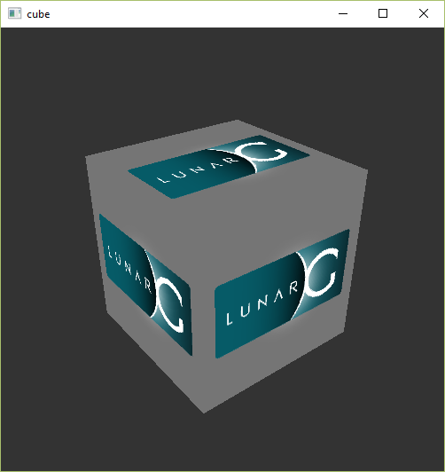
If you receive an error message then ensure that your drivers are up-to-date, include the Vulkan runtime and that your graphics card is supported. See the introduction chapter for links to drivers from the major vendors.
There is another program in this directory that will be useful for development. The glslangValidator.exe and glslc.exe programs will be used to compile shaders from the human-readable GLSL to bytecode. We'll cover this in depth in the shader modules chapter. The Bin directory also contains the binaries of the Vulkan loader and the validation layers, while the Lib directory contains the libraries.
Feel free to explore the other files, but we won't need them for this tutorial.
Linux
These instructions will be aimed at Ubuntu users, but you may be able to follow along by changing the apt commands to the package manager commands that are appropriate for you.
The most important components you'll need for developing Vulkan applications on Linux are the Vulkan loader, validation layers, and a couple of command-line utilities to test whether your machine is Vulkan-capable:
sudo apt install vulkan-tools– Command-line utilities, most importantlyvulkaninfoandvkcube. Run these to confirm your machine supports Vulkan.sudo apt install libvulkan-dev– Installs Vulkan loader. The loader looks up the functions in the driver at runtime, similarly to GLEW for OpenGL - if you're familiar with that.sudo apt install vulkan-validationlayers-dev– Installs the standard validation layers. These are crucial when debugging Vulkan applications, and we'll discuss them in an upcoming chapter.
If installation was successful, you should be all set with the Vulkan portion. Remember to run vkcube and ensure you see the following pop up in a window:
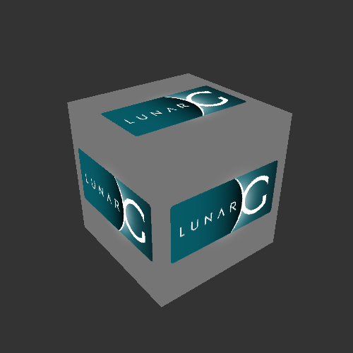
If you receive an error message then ensure that your drivers are up-to-date, include the Vulkan runtime and that your graphics card is supported. See the introduction chapter for links to drivers from the major vendors.
macOS
TODO: Author does not use macOS and cannot provide instructions. If you have reproducible instructions for macOS, please submit a pull request.
FAQ
This page lists solutions to common problems that you may encounter while developing Vulkan applications.
-
I get an access violation error in the core validation layer – Make sure that MSI Afterburner / RivaTuner Statistics Server is not running, because it has some compatibility problems with Vulkan.
-
I don't see any messages from the validation layers / Validation layers are not available – First make sure that the validation layers get a chance to print errors by keeping the terminal open after your program exits. You can do this from Visual Studio by running your program with Ctrl-F5 instead of F5, and on Linux by executing your program from a terminal window. If there are still no messages and you are sure that validation layers are turned on, then you should ensure that your Vulkan SDK is correctly installed by following the "Verify the Installation" instructions on this page. Also ensure that your SDK version is at least 1.1.106.0 to support the
VK_LAYER_KHRONOS_validationlayer. -
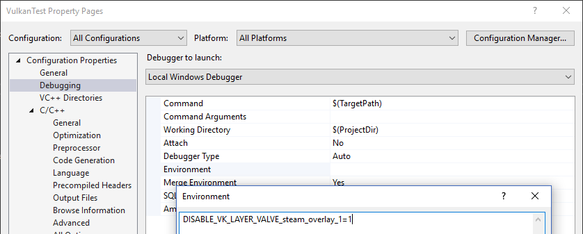
vkCreateSwapchainKHR triggers an error in SteamOverlayVulkanLayer64.dll – This appears to be a compatibility problem in the Steam client beta. There are a few possible workarounds:
- Opt out of the Steam beta program.
- Set the
DISABLE_VK_LAYER_VALVE_steam_overlay_1environment variable to1 - Delete the Steam overlay Vulkan layer entry in the registry under
HKEY_LOCAL_MACHINE\SOFTWARE\Khronos\Vulkan\ImplicitLayers
Example:
Base code
General structure
In the previous chapter you've created a Vulkan project with all of the proper configuration and tested it with the sample code. In this chapter we're starting from scratch with the following code:
class Application {
    public void run() {
        initVulkan();
        mainLoop();
        cleanup();
    }

    private void initVulkan() {
    }

    private void mainLoop() {
    }

    private void cleanup() {
    }
}

public class Main {
    public static void main(String[] args) {
        try {
            var app = new Application();
            app.run();
        }
        catch (Throwable e) {
            e.printStackTrace(System.err);
        }
    }
}
The program itself is wrapped into a class where we'll store the Vulkan objects as private class members and add functions to initiate each of them, which will be called from the initVulkan function. Once everything has been prepared, we enter the main loop to start rendering frames. We'll fill in the mainLoop function to include a loop that iterates until the window is closed in a moment. Once the window is closed and mainLoop returns, we'll make sure to deallocate the resources we've used in the cleanup function.
If any kind of fatal error occurs during execution then we'll throw a RuntimeException exception with a descriptive message, which will propagate back to the main function and be printed to the command prompt. To handle a variety of standard exception types as well, we catch the more general java.lang.Throwable. One example of an error that we will deal with soon is finding out that a certain required extension is not supported.
Roughly every chapter that follows after this one will add one new function that will be called from initVulkan and one or more new Vulkan objects to the private class members that need to be freed at the end in cleanup.
Resource management
Just like each chunk of memory allocated with malloc requires a call to free, every Vulkan object that we create needs to be explicitly destroyed when we no longer need it. While in Java there are several ways to manage resources automatically, however, I've chosen to be explicit about allocation and deallocation of Vulkan objects in this tutorial. After all, Vulkan's niche is to be explicit about every operation to avoid mistakes, so it's good to be explicit about the lifetime of objects to learn how the API works.
After following this tutorial, you could implement automatic resource management by writing Java classes that acquire Vulkan objects in their constructor and release them in maybe Autoclosable::close, depending on your ownership requirements. RAII is the recommended model for larger Vulkan programs, but for learning purposes it's always good to know what's going on behind the scenes.
Vulkan objects are either created directly with functions like vkCreateXXX, or allocated through another object with functions like vkAllocateXXX. After making sure that an object is no longer used anywhere, you need to destroy it with the counterparts vkDestroyXXX and vkFreeXXX. The parameters for these functions generally vary for different types of objects, but there is one parameter that they all share: pAllocator. This is an optional parameter that allows you to specify callbacks for a custom memory allocator. We will ignore this parameter in the tutorial and always pass null as argument.
Initializing GLFW
Vulkan works perfectly fine without creating a window if you want to use it for off-screen rendering, but it's a lot more exciting to actually show something! Add a initWindow function and add a call to it from the run function before the other calls. We'll use that function to initialize GLFW and create a window.
public void run() {
    initWindow();
    initVulkan();
    mainLoop();
    cleanup();
}

private void initWindow() {
}
Unlike in LWJGL or some other wrappers, with vulkan4j, you need to manually load both library and the library functions. Firstly we need to load GLFW native library into the JVM. This can be done with a single line of code:
GLFWLoader.loadGLFWLibrary();
Then we want to load the GLFW functions. Add a private field to the Application class:
private GLFW glfw;
And then initialize it in the initWindow function:
private void initWindow() {
    // ...
    glfw = GLFWLoader.loadGLFW();
}
Then we can call glfwInit() to initialize the GLFW library. If it fails, we'll throw an exception:
if (glfw.glfwInit() != GLFWConstants.GLFW_TRUE) {
    throw new RuntimeException("Failed to initialize GLFW");
}
Then we will check Vulkan support with glfwVulkanSupported():
if (glfw.glfwVulkanSupported() != GLFWConstants.GLFW_TRUE) {
    throw new RuntimeException("Vulkan is not supported");
}
Then we start giving GLFW hints about the window we want to create. Because GLFW was originally designed to create an OpenGL context, we need to tell it to not create an OpenGL context with a subsequent call:
glfw.glfwWindowHint(GLFWConstants.GLFW_CLIENT_API, GLFWConstants.GLFW_NO_API);
Because handling resized windows takes special care that we'll look into later, disable it for now with another window hint call:
glfw.glfwWindowHint(GLFWConstants.GLFW_RESIZABLE, GLFWConstants.GLFW_FALSE);
All that's left now is creating the actual window. Add a private class member to store the window handle:
private GLFWwindow window;
And then initialize it with glfwCreateWindow:
window = glfw.glfwCreateWindow(800, 600, ByteBuffer.allocateString(Arena.global(), "Vulkan"), null, null);
The first three parameters specify the width, height and title of the window. The fourth parameter allows you to optionally specify a monitor to open the window on and the last parameter is only relevant to OpenGL.
It's a good idea to use constants instead of hardcoded width and height numbers because we'll be referring to these values a couple of times in the future. Also, using constants helps reducing expression size. I've added the following constants in the Application class definition:
private static final int WIDTH = 800;
private static final int HEIGHT = 600;
private static final ByteBuffer WINDOW_TITLE = ByteBuffer.allocateString(Arena.global(), "Vulkan");
and replaced the window creation call with
window = glfw.glfwCreateWindow(WIDTH, HEIGHT, WINDOW_TITLE, null, null);
You should now have a initWindow function that looks like this:
private void initWindow() {
    GLFWLoader.loadGLFWLibrary();
    glfw = GLFWLoader.loadGLFW();
    if (glfw.glfwInit() != GLFWConstants.GLFW_TRUE) {
        throw new RuntimeException("Failed to initialize GLFW");
    }

    if (glfw.glfwVulkanSupported() != GLFWConstants.GLFW_TRUE) {
        throw new RuntimeException("Vulkan is not supported");
    }

    glfw.glfwWindowHint(GLFWConstants.GLFW_CLIENT_API, GLFWConstants.GLFW_NO_API);
    glfw.glfwWindowHint(GLFWConstants.GLFW_RESIZABLE, GLFWConstants.GLFW_FALSE);
    window = glfw.glfwCreateWindow(WIDTH, HEIGHT, WINDOW_TITLE, null, null);
}
To keep the application running until either an error occurs or the window is closed, we need to add an event loop to the mainLoop function as follows:
private void mainLoop() {
    while (glfw.glfwWindowShouldClose(window) == GLFWConstants.GLFW_FALSE) {
        glfw.glfwPollEvents();
    }
}
This code should be fairly self-explanatory. It loops and checks for events like pressing the X button until the window has been closed by the user. This is also the loop where we'll later call a function to render a single frame.
Once the window is closed, we need to clean up resources by destroying it and terminating GLFW itself. This will be our first cleanup code:
private void cleanup() {
    glfw.glfwDestroyWindow(window);
    glfw.glfwTerminate();
}
When you run the program now you should see a window titled Vulkan show up until the application is terminated by closing the window. Now that we have the skeleton for the Vulkan application, let's create the first Vulkan object!
Instance
Loading Vulkan library
Before we can start using Vulkan, we need to load the Vulkan library and several fundamental Vulkan commands, just like what we did with GLFW. Add the following private fields to the Application class:
private StaticCommands staticCommands;
private EntryCommands entryCommands;
Then load Vulkan library and initialize these two fields in the initVulkan function:
void initVulkan() {
    VulkanLoader.loadVulkanLibrary();
    staticCommands = VulkanLoader.loadStaticCommands();
    entryCommands = VulkanLoader.loadEntryCommands();
}
Creating an instance
The first step to use Vulkan is to create an instance. The instance is the connection between your application and the Vulkan library and creating it involves specifying some details about your application to the driver.
Start by adding a createInstance function and invoke it in the initVulkan Function.
void initVulkan() {
    // ...
    createInstance();
}
Additionally add a data member to hold the handle to the instance:
private VkInstance instance;
Now, to create an instance we'll first have to fill in a struct with some information about our application. This data is technically optional, but it may provide some useful information to the driver in order to optimize our specific application (e.g. because it uses a well-known graphics engine with certain special behavior). This struct is called VkApplicationInfo:
private void createInstance() {
    try (var arena = Arena.ofConfined()) {
        var appInfo = VkApplicationInfo.allocate(arena);
        appInfo.pApplicationName(ByteBuffer.allocateString(arena, "Zdravstvuyte, Vulkan!"));
        appInfo.applicationVersion(Version.vkMakeAPIVersion(0, 1, 0, 0));
        appInfo.pEngineName(ByteBuffer.allocateString(arena, "Soloviev D-30"));
        appInfo.engineVersion(Version.vkMakeAPIVersion(0, 1, 0, 0));
        appInfo.apiVersion(Version.VK_API_VERSION_1_0);
    }
}
If you're not familiar with the
tryblock syntax, it's a feature of Java 9 called "try-with-resources". It's used to automatically close resources that implement theAutoCloseableinterface. In this case, theArenaobject is a resource that will be automatically closed when the block is exited.
Vulkan C API requires you to explicitly specify the type in the sType member. However, vulkan4j has already taken care of this for you. The VkApplicationInfo.allocate method will fill in the sType field after allocating the struct. What's more, Arena.ofConfined() creates an arena whose allocate method will automatically fill allocated memory with zeros, so we don't need to zero-initialize the rest of the struct fields one by one.
A lot of information in Vulkan is passed through structs instead of function parameters and we'll have to fill in one more struct to provide sufficient information for creating an instance. This next struct is not optional and tells the Vulkan driver which global extensions and validation layers we want to use. Global here means that they apply to the entire program and not a specific device, which will become clear in the next few chapters.
var instanceCreateInfo = VkInstanceCreateInfo.allocate(arena);
instanceCreateInfo.pApplicationInfo(appInfo);
The first field pApplicationInfo is straightforward. The next two fields specify the desired global extensions. As mentioned in the overview chapter, Vulkan is a platform-agnostic API, which means that you need an extension to interface with the window system. GLFW has a handy built-in function that returns the extension(s) it needs to do that which we can pass to the struct:
var pGLFWExtensionCount = IntBuffer.allocate(arena);
var glfwExtensions = glfw.glfwGetRequiredInstanceExtensions(pGLFWExtensionCount);
if (glfwExtensions == null) {
    throw new RuntimeException("Failed to get GLFW required instance extensions");
}

var glfwExtensionCount = pGLFWExtensionCount.read();
glfwExtensions = glfwExtensions.reinterpret(glfwExtensionCount);
instanceCreateInfo.enabledExtensionCount(glfwExtensionCount);
instanceCreateInfo.ppEnabledExtensionNames(glfwExtensions);
Note: here we call
reinterpreton theglfwExtensionsbuffer to mark its size asglfwExtensionCount. We need to do this on ourselves because the auto-generated bindings don't know how to correctly set the size of the buffer when it's returned from a function. For now this step is not necessary yet, becausevkCreateInstancedoesn't need the size information of ourPointerBuffer-- it acquires the size from theVkInstanceCreateInfo::enabledExtensionCountfield instead. However, in the following chapaters we'll readglfwExtensionsfrom Java code, and we'll need correct size information.
instanceCreateInfo.enabledLayerCount(0);
We've now specified everything Vulkan needs to create an instance and we can finally issue the vkCreateInstance call:
var pInstance = VkInstance.Buffer.allocate(arena);
var result = entryCommands.vkCreateInstance(instanceCreateInfo, null, pInstance);
if (result != VkResult.VK_SUCCESS) {
    throw new RuntimeException("Failed to create instance, vulkan error code: " + VkResult.explain(result));
}
instance = pInstance.read();
As you'll see, the general pattern that object creation function parameters in Vulkan follow is:
- Pointer to struct with creation info
- Pointer to custom allocator callbacks, always
nullin this tutorial - Pointer to the variable that stores the handle to the new object
If everything went well then the handle to the instance was stored in the VkInstance class member. Nearly all Vulkan functions return a value of type VkResult that is either VK_SUCCESS or an error code.
Loading instance level Vulkan commands
After creating the instance, we can load the instance level Vulkan commands. Add a new field to the Application class:
private InstanceCommands instanceCommands;
Then load the instance level commands in the initVulkan function:
instanceCommands = VulkanLoader.loadInstanceCommands(instance, staticCommands);
Checking for extension support
If you look at the vkCreateInstance documentation then you'll see that one of the possible error codes is VK_ERROR_EXTENSION_NOT_PRESENT. We could simply specify the extensions we require and terminate if that error code comes back. That makes sense for essential extensions like the window system interface, but what if we want to check for optional functionality?
To retrieve a list of supported extensions before creating an instance, there's the vkEnumerateInstanceExtensionProperties function. It takes a pointer to a variable that stores the number of extensions and an array of VkExtensionProperties to store details of the extensions. It also takes an optional first parameter that allows us to filter extensions by a specific validation layer, which we'll ignore for now.
To allocate an array to hold the extension details we first need to know how many there are. You can request just the number of extensions by leaving the latter parameter empty:
IntBuffer pExtensionCount = IntBuffer.allocate(arena);
var result = entryCommands.vkEnumerateInstanceExtensionProperties(null, pExtensionCount, null);
if (result != VkResult.VK_SUCCESS) {
    throw new RuntimeException("Failed to enumerate instance extension properties, vulkan error code: " + VkResult.explain(result));
}
var extensionCount = pExtensionCount.read();
Now allocate an array to hold the extension details:
var extensions = VkExtensionProperties.allocate(arena, extensionCount);
result = entryCommands.vkEnumerateInstanceExtensionProperties(null, pExtensionCount, extensions[0]);
if (result != VkResult.VK_SUCCESS) {
    throw new RuntimeException("Failed to enumerate instance extension properties, vulkan error code: " + VkResult.explain(result));
}
Note: in
vulkan4j, when passing an array of structs/unions to a Vulkan function wrapper, you should pass the first element of the array.
Each VkExtensionProperties struct contains the name and version of an extension. We can list them with a simple for loop (\t is a tab for indentation):
for (var extension : extensions) {
    System.out.println("\t" + extension.extensionName().readString());
}
You can add this code to the createInstance function if you'd like to provide some details about the Vulkan support. As a challenge, try to create a function that checks if all the extensions returned by glfwGetRequiredInstanceExtensions are included in the supported extensions list.
Cleaning up
The VkInstance should be only destroyed right before the program exits. It can be destroyed in cleanup with the vkDestroyInstance function:
void cleanup() {
    instanceCommands.vkDestroyInstance(instance, null);
    // ...
}
The parameters for the vkDestroyInstance function are straightforward. As mentioned in the previous chapter, the allocation and deallocation functions in Vulkan have an optional allocator callback that we'll ignore by passing null to it. All the other Vulkan resources that we'll create in the following chapters should be cleaned up before the instance is destroyed.
Before continuing with the more complex steps after instance creation, it's time to evaluate our debugging options by checking out validation layers.
Validation layers
What are validation layers?
The Vulkan API is designed around the idea of minimal driver overhead and one of the manifestations of that goal is that there is very limited error checking in the API by default. Even mistakes as simple as setting enumerations to incorrect values or passing null pointers to required parameters are generally not explicitly handled and will simply result in crashes or undefined behavior. Because Vulkan requires you to be very explicit about everything you're doing, it's easy to make many small mistakes like using a new GPU feature and forgetting to request it at logical device creation time.
However, that doesn't mean that these checks can't be added to the API. Vulkan introduces an elegant system for this known as validation layers. Validation layers are optional components that hook into Vulkan function calls to apply additional operations. Common operations in validation layers are:
- Checking the values of parameters against the specification to detect misuse
- Tracking creation and destruction of objects to find resource leaks
- Checking thread safety by tracking the threads that calls originate from
- Logging every call and its parameters to the standard output
- Tracing Vulkan calls for profiling and replaying
Here's an example of what the implementation of a function in a diagnostics validation layer could look like:
VkResult vkCreateInstance(
    const VkInstanceCreateInfo* pCreateInfo,
    const VkAllocationCallbacks* pAllocator,
    VkInstance* instance
) {

    if (pCreateInfo == NULL || instance == NULL) {
        log("Null pointer passed to required parameter!");
        return VK_ERROR_INITIALIZATION_FAILED;
    }

    return real_vkCreateInstance(pCreateInfo, pAllocator, instance);
}
These validation layers can be freely stacked to include all the debugging functionality that you're interested in. You can simply enable validation layers for debug builds and completely disable them for release builds, which gives you the best of both worlds!
Vulkan does not come with any validation layers built-in, but the LunarG Vulkan SDK provides a nice set of layers that check for common errors. They're also completely open source, so you can check which kind of mistakes they check for and contribute. Using the validation layers is the best way to avoid your application breaking on different drivers by accidentally relying on undefined behavior.
Validation layers can only be used if they have been installed onto the system. For example, the LunarG validation layers are only available on PCs with the Vulkan SDK installed.
There were formerly two different types of validation layers in Vulkan: instance and device specific. The idea was that instance layers would only check calls related to global Vulkan objects like instances, and device specific layers would only check calls related to a specific GPU. Device specific layers have now been deprecated, which means that instance validation layers apply to all Vulkan calls. The specification document still recommends that you enable validation layers at device level as well for compatibility, which is required by some implementations. We'll simply specify the same layers as the instance at logical device level, which we'll see later on.
Using validation layers
In this section we'll see how to enable the standard diagnostics layers provided by the Vulkan SDK. Just like extensions, validation layers need to be enabled by specifying their name. All the useful standard validation is bundled into a layer included in the SDK that is known as VK_LAYER_KHRONOS_validation.
Let's first add a configuration variable to specify whether to enable validation layers or not. I've chosen to base the value on a JVM option. Add the following field to the Application class:
private static final boolean ENABLE_VALIDATION_LAYERS = System.getProperty("validation") != null;
Validation layers will be enabled if the JVM option validation is set. If you're using an IDE, you can add this option in the run configuration.
Then let's also make validation layer name a named constant:
private static String VALIDATION_LAYER_NAME = "VK_LAYER_KHRONOS_validation";
We'll add a new function checkValidationLayerSupport that checks if the validation layer we want to use is available. First list all the available layers using the vkEnumerateInstanceLayerProperties function.
private boolean checkValidationLayerSupport() {
    try (var arena = Arena.ofConfined()) {
        var pLayerCount = IntBuffer.allocate(arena);
        var result = entryCommands.vkEnumerateInstanceLayerProperties(pLayerCount, null);
        if (result != VkResult.VK_SUCCESS) {
            throw new RuntimeException("Failed to enumerate instance layer properties, vulkan error code: " + VkResult.explain(result));
        }

        var layerCount = pLayerCount.read();
        var availableLayers = VkLayerProperties.allocate(arena, layerCount);
        result = entryCommands.vkEnumerateInstanceLayerProperties(pLayerCount, availableLayers[0]);
        if (result != VkResult.VK_SUCCESS) {
            throw new RuntimeException("Failed to enumerate instance layer properties, vulkan error code: " + VkResult.explain(result));
        }

        return false;
    }
}
Next, check if our desired layer name exists in the list of available layers:
// ...

for (var layer : availableLayers) {
    if (VALIDATION_LAYER_NAME.equals(layer.layerName().readString())) {
        return true;
    }
}

return false;
We can now use this function in createInstance:
if (ENABLE_VALIDATION_LAYERS && !checkValidationLayerSupport()) {
    throw new RuntimeException("Validation layers requested, but not available!");
}

// ...
Now run the program in debug mode and ensure that the error does not occur. If it does, then have a look at the FAQ.
Finally, modify the VkInstanceCreateInfo struct instantiation to include the validation layer names if they are enabled:
if (ENABLE_VALIDATION_LAYERS) {
    instanceCreateInfo.enabledLayerCount(1);
    PointerBuffer ppEnabledLayerNames = PointerBuffer.allocate(arena);
    ppEnabledLayerNames.write(ByteBuffer.allocateString(arena, VALIDATION_LAYER_NAME));
    instanceCreateInfo.ppEnabledLayerNames(ppEnabledLayerNames);
}
If the check was successful then vkCreateInstance should not ever return a VK_ERROR_LAYER_NOT_PRESENT error, but you should run the program to make sure.
Message callback
The validation layers will print debug messages to the standard output by default, but we can also handle them ourselves by providing an explicit callback in our program. This will also allow you to decide which kind of messages you would like to see, because not all are necessarily (fatal) errors. If you don't want to do that right now then you may skip to the last section in this chapter.
To set up a callback in the program to handle messages and the associated details, we have to set up a debug messenger with a callback using the VK_EXT_debug_utils extension.
We'll first create a getRequiredExtensions function that will return the required list of extensions based on whether validation layers are enabled or not:
private PointerBuffer getRequiredExtensions(Arena arena) {
    try (var localArena = Arena.ofConfined()) {
        var pGLFWExtensionCount = IntBuffer.allocate(localArena);
        var glfwExtensions = glfw.glfwGetRequiredInstanceExtensions(pGLFWExtensionCount);
        if (glfwExtensions == null) {
            throw new RuntimeException("Failed to get GLFW required instance extensions");
        }

        var glfwExtensionCount = pGLFWExtensionCount.read();
        glfwExtensions = glfwExtensions.reinterpret(glfwExtensionCount);
        if (!ENABLE_VALIDATION_LAYERS) {
            return glfwExtensions;
        }
        else {
            var extensions = PointerBuffer.allocate(arena, glfwExtensionCount + 1);
            for (int i = 0; i < glfwExtensionCount; i++) {
                extensions.write(i, glfwExtensions.read(i));
            }

            extensions.write(glfwExtensionCount, ByteBuffer.allocateString(arena, Constants.VK_EXT_DEBUG_UTILS_EXTENSION_NAME));
            return extensions;
        }
    }
}
Note: here we want the created
PointerBufferto be valid after returning from the function, so we'll allocate it with a caller-providedArena.
The extensions specified by GLFW are always required, but the debug messenger extension is conditionally added. Note that I've used the Constants.VK_EXT_DEBUG_UTILS_EXTENSION_NAME constant here which is equal to the literal string "VK_EXT_debug_utils". Using this named constant lets you avoid typos.
We can now use this function in createInstance:
var extensions = getRequiredExtensions(arena);
instanceCreateInfo.enabledExtensionCount((int) extensions.size());
instanceCreateInfo.ppEnabledExtensionNames(extensions);
Run the program to make sure you don't receive a VK_ERROR_EXTENSION_NOT_PRESENT error. We don't really need to check for the existence of this extension, because it should be implied by the availability of the validation layers.
Now let's see what a debug callback function looks like. Add a new static member function called debugCallback like such:
private static /* VkBool32 */ int debugCallback(
        @enumtype(VkDebugUtilsMessageSeverityFlagsEXT.class) int messageSeverity,
        @enumtype(VkDebugUtilsMessageTypeFlagsEXT.class) int messageType,
        @pointer(comment="const VkDebugUtilsMessengerCallbackDataEXT*") MemorySegment pCallbackData,
        @pointer(comment="void*") MemorySegment pUserData
) {
    var callbackData = new VkDebugUtilsMessengerCallbackDataEXT(pCallbackData.reinterpret(VkDebugUtilsMessengerCallbackDataEXT.SIZE));
    System.err.println("Validation layer: " + Objects.requireNonNull(callbackData.pMessage()).readString());
    return Constants.VK_FALSE;
}
Note1: since Vulkan will directly call our callback function, it is not possible to use wrapper types like
VkDebugUtilsMessengerCallbackDataEXTdirectly. Instead, we'll use theMemorySegmenttype to accept the raw pointer and then wrap it in theVkDebugUtilsMessengerCallbackDataEXTclass on ourselves. To convince that theMemorySegmentis a pointer to the correct struct, we'll use thereinterpretmethod to cast it to the correct size, so JVM won't complain about buffer overflow in future accesses.
Note2: the
@enumtypeannotations are completely optional, but useful indicating the expected type of the integer values. Also this makes Ctrl-clicking navigation in IDEs work.
The first parameter specifies the severity of the message, which is one of the following flags:
VK_DEBUG_UTILS_MESSAGE_SEVERITY_VERBOSE_BIT_EXT: Diagnostic messageVK_DEBUG_UTILS_MESSAGE_SEVERITY_INFO_BIT_EXT: Informational message like the creation of a resourceVK_DEBUG_UTILS_MESSAGE_SEVERITY_WARNING_BIT_EXT: Message about behavior that is not necessarily an error, but very likely a bug in your applicationVK_DEBUG_UTILS_MESSAGE_SEVERITY_ERROR_BIT_EXT: Message about behavior that is invalid and may cause crashes
The values of this enumeration are set up in such a way that you can use a comparison operation to check if a message is equal or worse compared to some level of severity, for example:
if (messageSeverity >= VkDebugUtilsMessageSeverityFlagsEXT.VK_DEBUG_UTILS_MESSAGE_SEVERITY_WARNING_BIT_EXT) {
    // Message is important enough to show
}
The messageType parameter can have the following values:
VK_DEBUG_UTILS_MESSAGE_TYPE_GENERAL_BIT_EXT: Some event has happened that is unrelated to the specification or performanceVK_DEBUG_UTILS_MESSAGE_TYPE_VALIDATION_BIT_EXT: Something has happened that violates the specification or indicates a possible mistakeVK_DEBUG_UTILS_MESSAGE_TYPE_PERFORMANCE_BIT_EXT: Potential non-optimal use of Vulkan
The pCallbackData parameter refers to a VkDebugUtilsMessengerCallbackDataEXT struct containing the details of the message itself, with the most important members being:
pMessage: The debug message as a null-terminated stringpObjects: Array of Vulkan object handles related to the messageobjectCount: Number of objects in array
Finally, the pUserData parameter contains a pointer that was specified during the setup of the callback and allows you to pass your own data to it.
The callback returns a boolean that indicates if the Vulkan call that triggered the validation layer message should be aborted. If the callback returns true, then the call is aborted with the VK_ERROR_VALIDATION_FAILED_EXT error. This is normally only used to test the validation layers themselves, so you should always return VK_FALSE.
Creating a upcall stub
Now our debugCallback is a Java function. In order to make it a ready-to-use C function pointer, we need several extra steps. First, we need a function descriptor:
private static final FunctionDescriptor DESCRIPTOR_debugCallback = FunctionDescriptor.of(
        ValueLayout.JAVA_INT, // return value VkBool32
        ValueLayout.JAVA_INT, // int messageSeverity
        ValueLayout.JAVA_INT, // int messageType
        ValueLayout.ADDRESS, // const VkDebugUtilsMessengerCallbackDataEXT* pCallbackData
        ValueLayout.ADDRESS  // void* pUserData
);
Then we need to retrieve the method handle to debugCallback:
private static final MethodHandle HANDLE_debugCallback;
static {
    try {
        HANDLE_debugCallback = MethodHandles
                .lookup()
                .findStatic(Application.class, "debugCallback", DESCRIPTOR_debugCallback.toMethodType());
    } catch (Exception e) {
        throw new RuntimeException(e);
    }
}
Finally, we create a upcall-ready MemorySegment with Linker
private static final MemorySegment UPCALL_debugCallback = Linker
        .nativeLinker()
        .upcallStub(HANDLE_debugCallback, DESCRIPTOR_debugCallback, Arena.global());
All that remains now is telling Vulkan about the callback function. Perhaps somewhat surprisingly, even the debug callback in Vulkan is managed with a handle that needs to be explicitly created and destroyed. Such a callback is part of a debug messenger and you can have as many of them as you want. Add a class member for this handle right under instance:
private VkDebugUtilsMessengerEXT debugMessenger;
Now add a function setupDebugMessenger to be called from initVulkan right after createInstance:
private void initVulkan() {
    // ...

    createInstance();
    setupDebugMessenger();
}

private void setupDebugMessenger() {
    if (!ENABLE_VALIDATION_LAYERS) {
        return;
    }
}
We'll need to fill in a structure with details about the messenger and its callback:
try (var arena = Arena.ofConfined()) {
    var debugUtilsMessengerCreateInfo = VkDebugUtilsMessengerCreateInfoEXT.allocate(arena);
    debugUtilsMessengerCreateInfo.messageSeverity(
            VkDebugUtilsMessageSeverityFlagsEXT.VK_DEBUG_UTILS_MESSAGE_SEVERITY_VERBOSE_BIT_EXT |
                    VkDebugUtilsMessageSeverityFlagsEXT.VK_DEBUG_UTILS_MESSAGE_SEVERITY_WARNING_BIT_EXT |
                    VkDebugUtilsMessageSeverityFlagsEXT.VK_DEBUG_UTILS_MESSAGE_SEVERITY_ERROR_BIT_EXT
    );
    debugUtilsMessengerCreateInfo.messageType(
            VkDebugUtilsMessageTypeFlagsEXT.VK_DEBUG_UTILS_MESSAGE_TYPE_GENERAL_BIT_EXT |
                    VkDebugUtilsMessageTypeFlagsEXT.VK_DEBUG_UTILS_MESSAGE_TYPE_VALIDATION_BIT_EXT |
                    VkDebugUtilsMessageTypeFlagsEXT.VK_DEBUG_UTILS_MESSAGE_TYPE_PERFORMANCE_BIT_EXT
    );
    debugUtilsMessengerCreateInfo.pfnUserCallback(UPCALL_debugCallback);
}
The messageSeverity field allows you to specify all the types of severities you would like your callback to be called for. I've specified all types except for VK_DEBUG_UTILS_MESSAGE_SEVERITY_INFO_BIT_EXT here to receive notifications about possible problems while leaving out verbose general debug info.
Similarly the messageType field lets you filter which types of messages your callback is notified about. I've simply enabled all types here. You can always disable some if they're not useful to you.
Finally, the pfnUserCallback field specifies the pointer to the callback function. You can optionally pass a pointer to the pUserData field which will be passed along to the callback function via the pUserData parameter.
Note that there are many more ways to configure validation layer messages and debug callbacks, but this is a good setup to get started with for this tutorial. See the extension specification for more info about the possibilities.
This struct should be passed to the vkCreateDebugUtilsMessengerEXT function to create the VkDebugUtilsMessengerEXT object.
var pDebugMessenger = VkDebugUtilsMessengerEXT.Buffer.allocate(arena);
var result = instanceCommands.vkCreateDebugUtilsMessengerEXT(
        instance,
        debugUtilsMessengerCreateInfo,
        null,
        pDebugMessenger
);
if (result != VkResult.VK_SUCCESS) {
    throw new RuntimeException("Failed to set up debug messenger, vulkan error code: " + VkResult.explain(result));
}
debugMessenger = pDebugMessenger.read();
The second to last parameter is again the optional allocator callback that we set to null, other than that the parameters are fairly straightforward. Since the debug messenger is specific to our Vulkan instance and its layers, it needs to be explicitly specified as first argument. You will also see this pattern with other child objects later on.
The VkDebugUtilsMessengerEXT object also needs to be cleaned up with a call to vkDestroyDebugUtilsMessengerEXT.
void cleanup() {
    if (ENABLE_VALIDATION_LAYERS) {
        instanceCommands.vkDestroyDebugUtilsMessengerEXT(instance, debugMessenger, null);
    }

    // ...
}
Debugging instance creation and destruction
Although we've now added debugging with validation layers to the program we're not covering everything quite yet. The vkCreateDebugUtilsMessengerEXT call requires a valid instance to have been created and vkDestroyDebugUtilsMessengerEXT must be called before the instance is destroyed. This currently leaves us unable to debug any issues in the vkCreateInstance and vkDestroyInstance calls.
However, if you closely read the extension documentation, you'll see that there is a way to create a separate debug utils messenger specifically for those two function calls. It requires you to simply pass a pointer to a VkDebugUtilsMessengerCreateInfoEXT struct in the pNext extension field of VkInstanceCreateInfo. First extract population of the messenger create info into a separate function:
private void setupDebugMessenger() {
    // ...

    var debugUtilsMessengerCreateInfo = VkDebugUtilsMessengerCreateInfoEXT.allocate(arena);
    populateDebugMessengerCreateInfo(debugUtilsMessengerCreateInfo);

    // ...
}

private void populateDebugMessengerCreateInfo(VkDebugUtilsMessengerCreateInfoEXT debugUtilsMessengerCreateInfo) {
    debugUtilsMessengerCreateInfo.messageSeverity(
            VkDebugUtilsMessageSeverityFlagsEXT.VK_DEBUG_UTILS_MESSAGE_SEVERITY_VERBOSE_BIT_EXT |
                    VkDebugUtilsMessageSeverityFlagsEXT.VK_DEBUG_UTILS_MESSAGE_SEVERITY_WARNING_BIT_EXT |
                    VkDebugUtilsMessageSeverityFlagsEXT.VK_DEBUG_UTILS_MESSAGE_SEVERITY_ERROR_BIT_EXT
    );
    debugUtilsMessengerCreateInfo.messageType(
            VkDebugUtilsMessageTypeFlagsEXT.VK_DEBUG_UTILS_MESSAGE_TYPE_GENERAL_BIT_EXT |
                    VkDebugUtilsMessageTypeFlagsEXT.VK_DEBUG_UTILS_MESSAGE_TYPE_VALIDATION_BIT_EXT |
                    VkDebugUtilsMessageTypeFlagsEXT.VK_DEBUG_UTILS_MESSAGE_TYPE_PERFORMANCE_BIT_EXT
    );
    debugUtilsMessengerCreateInfo.pfnUserCallback(UPCALL_debugCallback);
}
We can now re-use this in the createInstance function:
private void createInstance() {
    // ...
    if (ENABLE_VALIDATION_LAYERS) {
        // ...

        var debugCreateInfo = VkDebugUtilsMessengerCreateInfoEXT.allocate(arena);
        populateDebugMessengerCreateInfo(debugCreateInfo);
        instanceCreateInfo.pNext(debugCreateInfo);
    }
}
By creating an additional debug messenger this way it will automatically be used during vkCreateInstance and vkDestroyInstance and cleaned up after that.
Testing
Now let's intentionally make a mistake to see the validation layers in action. Temporarily remove the call to DestroyDebugUtilsMessengerEXT in the cleanup function and run your program. Once it exits you should see something like this:
Validation layer: Validation Error: [ VUID-vkDestroyInstance-instance-00629 ] Object 0: handle = 0x27be19342d0, type = VK_OBJECT_TYPE_INSTANCE; Object 1: handle = 0xfd5b260000000001, type = VK_OBJECT_TYPE_DEBUG_UTILS_MESSENGER_EXT; | MessageID = 0x8b3d8e18 | OBJ ERROR : For VkInstance 0x27be19342d0[], VkDebugUtilsMessengerEXT 0xfd5b260000000001[] has not been destroyed. The Vulkan spec states: All child objects created using instance must have been destroyed prior to destroying instance (https://vulkan.lunarg.com/doc/view/1.3.250.0/windows/1.3-extensions/vkspec.html#VUID-vkDestroyInstance-instance-00629)
Validation layer: Validation Error: [ VUID-vkDestroyInstance-instance-00629 ] Object 0: handle = 0x27be19342d0, type = VK_OBJECT_TYPE_INSTANCE; Object 1: handle = 0xfd5b260000000001, type = VK_OBJECT_TYPE_DEBUG_UTILS_MESSENGER_EXT; | MessageID = 0x8b3d8e18 | OBJ ERROR : For VkInstance 0x27be19342d0[], VkDebugUtilsMessengerEXT 0xfd5b260000000001[] has not been destroyed. The Vulkan spec states: All child objects created using instance must have been destroyed prior to destroying instance (https://vulkan.lunarg.com/doc/view/1.3.250.0/windows/1.3-extensions/vkspec.html#VUID-vkDestroyInstance-instance-00629)
If you don't see any messages then check your installation.
If you want to see which call triggered a message, you can add a breakpoint to the message callback and look at the stack trace.
Configuration
There are a lot more settings for the behavior of validation layers than just the flags specified in the VkDebugUtilsMessengerCreateInfoEXT struct. Browse to the Vulkan SDK and go to the Config directory. There you will find a vk_layer_settings.txt file that explains how to configure the layers.
To configure the layer settings for your own application, copy the file to the working directory of your project and follow the instructions to set the desired behavior. However, for the remainder of this tutorial I'll assume that you're using the default settings.
Throughout this tutorial I'll be making a couple of intentional mistakes to show you how helpful the validation layers are with catching them and to teach you how important it is to know exactly what you're doing with Vulkan. Now it's time to look at Vulkan devices in the system.
Physical devices and queue families
Selecting a physical device
After initializing the Vulkan library through a VkInstance we need to look for and select a graphics card in the system that supports the features we need. In fact, we can select any number of graphics cards and use them simultaneously, but in this tutorial we'll stick to the first graphics card that suits our needs.
We'll add a function pickPhysicalDevice and add a call to it in the initVulkan function.
private void initVulkan() {
    // ...
    pickPhysicalDevice();
}

private void pickPhysicalDevice() {
}
The graphics card that we'll end up selecting will be stored in a VkPhysicalDevice handle that is added as a new class member. This object will be implicitly destroyed when the VkInstance is destroyed, so we won't need to do anything new in the cleanup function.
private VkPhysicalDevice physicalDevice;
Listing the graphics cards is very similar to listing extensions and starts with querying just the number. If there are 0 devices with Vulkan support then there is no point going further.
private void pickPhysicalDevice() {
    try (var arena = Arena.ofConfined()) {
        var pDeviceCount = IntBuffer.allocate(arena);
        var result = instanceCommands.vkEnumeratePhysicalDevices(instance, pDeviceCount, null);
        if (result != VkResult.VK_SUCCESS) {
            throw new RuntimeException("Failed to enumerate physical devices, vulkan error code: " + VkResult.explain(result));
        }

        var deviceCount = pDeviceCount.read();
        if (deviceCount == 0) {
            throw new RuntimeException("Failed to find GPUs with Vulkan support");
        }
    }
}
Otherwise, we can now allocate an array to hold all the VkPhysicalDevice handles.
var pDevices = VkPhysicalDevice.Buffer.allocate(arena, deviceCount);
result = instanceCommands.vkEnumeratePhysicalDevices(instance, pDeviceCount, pDevices);
if (result != VkResult.VK_SUCCESS) {
    throw new RuntimeException("Failed to enumerate physical devices, vulkan error code: " + VkResult.explain(result));
}
var devices = pDevices.readAll();
Now we need to evaluate each of them and check if they are suitable for the operations we want to perform, because not all graphics cards are created equal. For that we'll introduce a new function:
private boolean isDeviceSuitable(VkPhysicalDevice device) {
    return true;
}
And we'll check if any of the physical devices meet the requirements that we'll add to that function.
for (var device : devices) {
    if (isDeviceSuitable(device)) {
        physicalDevice = device;
        break;
    }
}

if (physicalDevice == null) {
    throw new RuntimeException("Failed to find a suitable GPU");
}
The next section will introduce the first requirements that we'll check for in the isDeviceSuitable function. As we'll start using more Vulkan features in the later chapters we will also extend this function to include more checks.
Base device suitability checks
To evaluate the suitability of a device we can start by querying for some details. Basic device properties like the name, type and supported Vulkan version can be queried using vkGetPhysicalDeviceProperties.
var properties = VkPhysicalDeviceProperties.allocate(arena);
instanceCommands.vkGetPhysicalDeviceProperties(device, properties);
The support for optional features like texture compression, 64-bit floats and multi viewport rendering (useful for VR) can be queried using vkGetPhysicalDeviceFeatures:
var features = VkPhysicalDeviceFeatures.allocate(arena);
instanceCommands.vkGetPhysicalDeviceFeatures(device, features);
There are more details that can be queried from devices that we'll discuss later concerning device memory and queue families (see the next section).
As an example, let's say we consider our application only usable for dedicated graphics cards that support geometry shaders. Then the isDeviceSuitable function would look like this:
private boolean isDeviceSuitable(VkPhysicalDevice device) {
    try (var arena = Arena.ofConfined()) {
        var properties = VkPhysicalDeviceProperties.allocate(arena);
        instanceCommands.vkGetPhysicalDeviceProperties(device, properties);

        var features = VkPhysicalDeviceFeatures.allocate(arena);
        instanceCommands.vkGetPhysicalDeviceFeatures(device, features);

        return properties.deviceType() == VkPhysicalDeviceType.VK_PHYSICAL_DEVICE_TYPE_DISCRETE_GPU &&
                features.geometryShader() == Constants.VK_TRUE;
    }
}
Instead of just checking if a device is suitable or not and going with the first one, you could also give each device a score and pick the highest one. That way you could favor a dedicated graphics card by giving it a higher score, but fall back to an integrated GPU if that's the only available one. Of course, you can also just display the names of the choices and allow the user to select.
Because we're just starting out, Vulkan support is the only thing we need, and therefore we'll settle for just any GPU:
private boolean isDeviceSuitable(VkPhysicalDevice device) {
    return true;
}
In the next section we'll discuss the first real required feature to check for.
Queue families
It has been briefly touched upon before that almost every operation in Vulkan, anything from drawing to uploading textures, requires commands to be submitted to a queue. There are different types of queues that originate from different queue families and each family of queues allows only a subset of commands. For example, there could be a queue family that only allows processing of compute commands or one that only allows memory transfer related commands.
We need to check which queue families are supported by the device and which one of these supports the commands that we want to use. For that purpose we'll add a new function findQueueFamilies that looks for all the queue families we need.
Right now we are only going to look for a queue that supports graphics commands, so the function could look like this:
private int findQueueFamilies(VkPhysicalDevice device) {
    // Logic to find graphics queue family
}
However, in one of the next chapters we're already going to look for yet another queue, so it's better to prepare for that and bundle the indices into a record:
private record QueueFamilyIndices(int graphicsFamily) {}

private QueueFamilyIndices findQueueFamilies(VkPhysicalDevice device) {
    // Logic to find queue family indices to create record with
}
The process of retrieving the list of queue families is exactly what you expect and uses vkGetPhysicalDeviceQueueFamilyProperties:
try (var arena = Arena.ofConfined()) {
    var pQueueFamilyCount = IntBuffer.allocate(arena);
        instanceCommands.vkGetPhysicalDeviceQueueFamilyProperties(device, pQueueFamilyCount, null);

    var queueFamilyCount = pQueueFamilyCount.read();
    var queueFamilies = VkQueueFamilyProperties.allocate(arena, queueFamilyCount);
        instanceCommands.vkGetPhysicalDeviceQueueFamilyProperties(device, pQueueFamilyCount, queueFamilies[0]);
}
The VkQueueFamilyProperties struct contains some details about the queue family, including the type of operations that are supported and the number of queues that can be created based on that family. We need to find at least one queue family that supports VK_QUEUE_GRAPHICS_BIT.
Integer graphicsFamily = null;
for (int i = 0; i < queueFamilyCount; i++) {
    if (queueFamilies[i].queueCount() > 0 && (queueFamilies[i].queueFlags() & VkQueueFlags.VK_QUEUE_GRAPHICS_BIT) != 0) {
        graphicsFamily = i;
        break;
    }
}

if (graphicsFamily != null) {
    return new QueueFamilyIndices(graphicsFamily);
}
else {
    return null;
}
Now that we have this fancy queue family lookup function, we can use it as a check in the isDeviceSuitable function to ensure that the device can process the commands we want to use:
private boolean isDeviceSuitable(VkPhysicalDevice device) {
    return findQueueFamilies(device) != null;
}
Great, that's all we need for now to find the right physical device! The next step is to create a logical device to interface with it.
Logical device and queues
Introduction
After selecting a physical device to use we need to set up a logical device to interface with it. The logical device creation process is similar to the instance creation process and describes the features we want to use. We also need to specify which queues to create now that we've queried which queue families are available. You can even create multiple logical devices from the same physical device if you have varying requirements.
Start by adding a new class member to store the logical device handle in.
private VkDevice device;
Next, add a createLogicalDevice function that is called from initVulkan.
private void initVulkan() {
    // ...
    createLogicalDevice();
}

private void createLogicalDevice() {
}
Specifying the queues to be created
The creation of a logical device involves specifying a bunch of details in structs again, of which the first one will be VkDeviceQueueCreateInfo. This structure describes the number of queues we want for a single queue family. Right now we're only interested in a queue with graphics capabilities.
var indices = findQueueFamilies(physicalDevice);
assert indices != null;

try (var arena = Arena.ofConfined()) {
    var queueCreateInfo = VkDeviceQueueCreateInfo.allocate(arena);
    queueCreateInfo.queueCount(1);
    queueCreateInfo.queueFamilyIndex(indices.graphicsFamily());
}
The currently available drivers will only allow you to create a small number of queues for each queue family, and you don't really need more than one. That's because you can create all the command buffers on multiple threads and then submit them all at once on the main thread with a single low-overhead call.
Vulkan lets you assign priorities to queues to influence the scheduling of command buffer execution using floating point numbers between 0.0 and 1.0. This is required even if there is only a single queue:
var pQueuePriorities = FloatBuffer.allocate(arena);
pQueuePriorities.write(1.0f);
queueCreateInfo.pQueuePriorities(pQueuePriorities);
Specifying used device features
The next information to specify is the set of device features that we'll be using. These are the features that we queried support for with vkGetPhysicalDeviceFeatures in the previous chapter, like geometry shaders. Right now we don't need anything special, so we can simply define it and leave everything to VK_FALSE. We'll come back to this structure once we're about to start doing more interesting things with Vulkan.
var deviceFeatures = VkPhysicalDeviceFeatures.allocate(arena);
Creating the logical device
With the previous two structures in place, we can start filling in the main VkDeviceCreateInfo structure. First add pointers to the queue creation info and the device features.
var deviceCreateInfo = VkDeviceCreateInfo.allocate(arena);
deviceCreateInfo.queueCreateInfoCount(1);
deviceCreateInfo.pQueueCreateInfos(queueCreateInfo);
deviceCreateInfo.pEnabledFeatures(deviceFeatures);
The remainder of the information bears a resemblance to the VkInstanceCreateInfo struct and requires you to specify extensions and validation layers. The difference is that these are device specific this time.
An example of a device specific extension is VK_KHR_swapchain, which allows you to present rendered images from that device to windows. It is possible that there are Vulkan devices in the system that lack this ability, for example because they only support compute operations. We will come back to this extension in the swap chain chapter.
Previous implementations of Vulkan made a distinction between instance and device specific validation layers, but this is no longer the case. That means that the enabledLayerCount and ppEnabledLayerNames fields of VkDeviceCreateInfo are ignored by up-to-date implementations. However, it is still a good idea to set them anyway to be compatible with older implementations:
if (ENABLE_VALIDATION_LAYERS) {
    deviceCreateInfo.enabledLayerCount(1);
    PointerBuffer ppEnabledLayerNames = PointerBuffer.allocate(arena);
    ppEnabledLayerNames.write(ByteBuffer.allocateString(arena, VALIDATION_LAYER_NAME));
    deviceCreateInfo.ppEnabledLayerNames(ppEnabledLayerNames);
}
We won't need any device specific extensions for now.
That's it, we're now ready to instantiate the logical device with a call to the appropriately named vkCreateDevice function.
var pDevice = VkDevice.Buffer.allocate(arena);
var result = instanceCommands.vkCreateDevice(physicalDevice, deviceCreateInfo, null, pDevice);
if (result != VkResult.VK_SUCCESS) {
    throw new RuntimeException("Failed to create logical device, vulkan error code: " + VkResult.explain(result));
}
device = pDevice.read();
The parameters are the physical device to interface with, the queue and usage info we just specified, the optional allocation callbacks pointer and a pointer to a variable to store the logical device handle in. Similarly to the instance creation function, this call can return errors based on enabling non-existent extensions or specifying the desired usage of unsupported features.
Loading device level Vulkan commands
After creating the device, we can load the device level Vulkan commands. Add a new field to the Application class:
private DeviceCommands deviceCommands;
Then load the device level commands in the createLogicalDevice function:
deviceCommands = VulkanLoader.loadDeviceCommands(instance, device, staticCommands);
Cleanup
The device should be destroyed in cleanup with the vkDestroyDevice function:
private void cleanup() {
    deviceCommands.vkDestroyDevice(device, null);
    // ...
}
Retrieving queue handles
The queues are automatically created along with the logical device, but we don't have a handle to interface with them yet. First add a class member to store a handle to the graphics queue:
private VkQueue graphicsQueue;
Device queues are implicitly cleaned up when the device is destroyed, so we don't need to do anything in cleanup.
We can use the vkGetDeviceQueue function to retrieve queue handles for each queue family. The parameters are the logical device, queue family, queue index and a pointer to the variable to store the queue handle in. Because we're only creating a single queue from this family, we'll simply use index 0.
var pQueue = VkQueue.Buffer.allocate(arena);
deviceCommands.vkGetDeviceQueue(device, indices.graphicsFamily(), 0, pQueue);
graphicsQueue = pQueue.read();
With the logical device and queue handles we can now actually start using the graphics card to do things! In the next few chapters we'll set up the resources to present results to the window system.
Window surface
Since Vulkan is a platform-agnostic API, it can not interface directly with the window system on its own. To establish the connection between Vulkan and the window system to present results to the screen, we need to use the WSI (Window System Integration) extensions. In this chapter we'll discuss the first one, which is VK_KHR_surface. It exposes a VkSurfaceKHR object that represents an abstract type of surface to present rendered images to. The surface in our program will be backed by the window that we've already opened with GLFW.
The VK_KHR_surface extension is an instance level extension and we've actually already enabled it, because it's included in the list returned by glfwGetRequiredInstanceExtensions. The list also includes some other WSI extensions that we'll use in the next couple of chapters.
The window surface needs to be created right after the instance creation, because it can actually influence the physical device selection. The reason we postponed this is that window surfaces are part of the larger topic of render targets and presentation for which the explanation would have cluttered the basic setup. It should also be noted that window surfaces are an entirely optional component in Vulkan, if you just need off-screen rendering. Vulkan allows you to do that without hacks like creating an invisible window (necessary for OpenGL).
Window surface creation
Start by adding a surface class member right below the debug callback.
private VkSurfaceKHR surface;
Although the VkSurfaceKHR object and its usage is platform-agnostic, its creation isn't because it depends on window system details. For example, it needs the HWND and HMODULE handles on Windows. Therefore, there is a platform-specific addition to the extension, which on Windows is called VK_KHR_win32_surface and is also automatically included in the list from glfwGetRequiredInstanceExtensions.
I will demonstrate how this platform specific extension can be used to create a surface on Windows, but we won't actually use it in this tutorial. It doesn't make any sense to use a library like GLFW and then proceed to use platform-specific code anyway. GLFW actually has glfwCreateWindowSurface that handles the platform differences for us. Still, it's good to see what it does behind the scenes before we start relying on it.
Because a window surface is a Vulkan object, it comes with a VkWin32SurfaceCreateInfoKHR struct that needs to be filled in. It has two important parameters: hwnd and hinstance. These are the handles to the window and the process.
try (var arena = Arena.ofConfined()) {
    var createInfo = VkWin32SurfaceCreateInfoKHR.allocate(arena)
            .hwnd(glfw.glfwGetWin32Window(window))
            .hinstance(libKernel32.GetModuleHandle(null));
}
The glfwGetWin32Window function is used to get the raw HWND from the GLFW window object. The GetModuleHandle call returns the HINSTANCE handle of the current process.
After that the surface can be created with vkCreateWin32SurfaceKHR, which includes a parameter for the instance, surface creation details, custom allocators and the variable for the surface handle to be stored in. Technically this is a WSI extension function, but it is so commonly used that the standard Vulkan loader includes it, so unlike other extensions you don't need to explicitly load it.
if (instanceCommands.vkCreateWin32SurfaceKHR(instance, createInfo.address(), null, pSurface) != VkResult.VK_SUCCESS) {
    throw new RuntimeError("Failed to create surface");
}
The process is similar for other platforms like Linux, where vkCreateXcbSurfaceKHR takes an XCB connection and window as creation details with X11.
The glfwCreateWindowSurface function performs exactly this operation with a different implementation for each platform. We'll now integrate it into our program. Add a function createSurface to be called from initVulkan right after instance creation and setupDebugMessenger.
private void initVulkan() {
    // ...
    setupDebugMessenger();
    createSurface();
    pickPhysicalDevice();
    // ...
}

private void createSurface() {
}
The GLFW call takes simple parameters instead of a struct which makes the implementation of the function very straightforward:
private void createSurface() {
    try (var arena = Arena.ofConfined()) {
        var pSurface = VkSurfaceKHR.Buffer.allocate(arena);
        var result = glfw.glfwCreateWindowSurface(instance, window, null, pSurface);
        if (result != VkResult.VK_SUCCESS) {
            throw new RuntimeException("Failed to create window surface, vulkan error code: " + VkResult.explain(result));
        }
        surface = pSurface.read();
    }
}
The parameters are the VkInstance, GLFW window pointer, custom allocators and pointer to VkSurfaceKHR variable. It simply passes through the VkResult from the relevant platform call. GLFW doesn't offer a special function for destroying a surface, but that can easily be done through the original API:
private void cleanup() {
    // ...
    instanceCommands.vkDestroySurfaceKHR(instance, surface, null);
    instanceCommands.vkDestroyInstance(instance, null);
    // ...
}
Make sure that the surface is destroyed before the instance.
Querying for presentation support
Although the Vulkan implementation may support window system integration, that does not mean that every device in the system supports it. Therefore we need to extend isDeviceSuitable to ensure that a device can present images to the surface we created. Since the presentation is a queue-specific feature, the problem is actually about finding a queue family that supports presenting to the surface we created.
It's actually possible that the queue families supporting drawing commands and the ones supporting presentation do not overlap. Therefore, we have to take into account that there could be a distinct presentation queue by modifying the QueueFamilyIndices record:
private record QueueFamilyIndices(int graphicsFamily, int presentFamily) {}
Next, we'll modify the findQueueFamilies function to look for a queue family that has the capability of presenting to our window surface. The function to check for that is vkGetPhysicalDeviceSurfaceSupportKHR, which takes the physical device, queue family index and surface as parameters. Add a call to it in the same loop as the VK_QUEUE_GRAPHICS_BIT:
Integer presentFamily = null;
var pSurfaceSupport = IntBuffer.allocate(arena);

for (int i = 0; i < queueFamilyCount; i++) {
    // ...

    if (pSurfaceSupport.read() == Constants.VK_TRUE) {
        presentFamily = i;
    }
}
Note that it's very likely that these end up being the same queue family after all, but throughout the program we will treat them as if they were separate queues for a uniform approach. Nevertheless, you could add logic to explicitly prefer a physical device that supports drawing and presentation in the same queue for improved performance.
Creating the presentation queue
The one thing that remains is modifying the logical device creation procedure to create the presentation queue and retrieve the VkQueue handle. Add a member variable for the handle:
private VkQueue presentQueue;
Next, we need to have multiple VkDeviceQueueCreateInfo structs to create a queue from both families. Modify the createLogicalDevice function to take the present family into account:
var deviceCreateInfo = VkDeviceCreateInfo.allocate(arena);
var pQueuePriorities = FloatBuffer.allocate(arena);
pQueuePriorities.write(1.0f);
if (indices.graphicsFamily == indices.presentFamily) {
    var queueCreateInfo = VkDeviceQueueCreateInfo.allocate(arena);
    queueCreateInfo.queueCount(1);
    queueCreateInfo.queueFamilyIndex(indices.graphicsFamily());
    queueCreateInfo.pQueuePriorities(pQueuePriorities);
    deviceCreateInfo.queueCreateInfoCount(1);
    deviceCreateInfo.pQueueCreateInfos(queueCreateInfo);
}
else {
    var queueCreateInfos = VkDeviceQueueCreateInfo.allocate(arena, 2);
    queueCreateInfos[0].queueCount(1);
    queueCreateInfos[0].queueFamilyIndex(indices.graphicsFamily());
    queueCreateInfos[0].pQueuePriorities(pQueuePriorities);
    queueCreateInfos[1].queueCount(1);
    queueCreateInfos[1].queueFamilyIndex(indices.presentFamily());
    queueCreateInfos[1].pQueuePriorities(pQueuePriorities);
    deviceCreateInfo.queueCreateInfoCount(2);
    deviceCreateInfo.pQueueCreateInfos(queueCreateInfos[0]);
}
Finally, add a call to retrieve the queue handle:
deviceCommands.vkGetDeviceQueue(device, indices.presentFamily(), 0, pQueue);
presentQueue = pQueue.read();
In case the queue families are the same, the two handles will most likely have the same value now. In the next chapter we're going to look at swap chains and how they give us the ability to present images to the surface.
Swap chain
Vulkan does not have the concept of a "default framebuffer", hence it requires an infrastructure that will own the buffers we will render to before we visualize them on the screen. This infrastructure is known as the swap chain and must be created explicitly in Vulkan. The swap chain is essentially a queue of images that are waiting to be presented to the screen. Our application will acquire such an image to draw to it, and then return it to the queue. How exactly the queue works and the conditions for presenting an image from the queue depend on how the swap chain is set up, but the general purpose of the swap chain is to synchronize the presentation of images with the refresh rate of the screen.
Checking for swap chain support
Not all graphics cards are capable of presenting images directly to a screen for various reasons, for example because they are designed for servers and don't have any display outputs. Secondly, since image presentation is heavily tied into the window system and the surfaces associated with windows, it is not actually part of the Vulkan core. You have to enable the VK_KHR_swapchain device extension after querying for its support.
For that purpose we'll first extend the isDeviceSuitable function to check if this extension is supported. We've previously seen how to list the extensions that are supported by a VkPhysicalDevice, so doing that should be fairly straightforward. Note that the vulkan4j provides a nice named constant Constants.VK_KHR_SWAPCHAIN_EXTENSION_NAME hat is defined as VK_KHR_swapchain. The advantage of using this named constant is that the compiler will catch misspellings.
Create a new function checkDeviceExtensionSupport that is called from isDeviceSuitable as an additional check:
private boolean isDeviceSuitable(VkPhysicalDevice device) {
    var indices = findQueueFamilies(device);
    var extensionsSupported = checkDeviceExtensionSupport(device);
    return (indices != null) && extensionsSupported;
}

boolean checkDeviceExtensionSupport(VkPhysicalDevice device) {
    return true;
}
Modify the body of the function to enumerate the extensions and check if all of the required extensions are amongst them.
private boolean checkDeviceExtensionSupport(VkPhysicalDevice device) {
    try (var arena = Arena.ofConfined()) {
        var pExtensionCount = IntBuffer.allocate(arena);
        var result = instanceCommands.vkEnumerateDeviceExtensionProperties(device, null, pExtensionCount, null);
        if (result != VkResult.VK_SUCCESS) {
            throw new RuntimeException("Failed to enumerate device extension properties, vulkan error code: " + VkResult.explain(result));
        }

        var extensionCount = pExtensionCount.read();
        var availableExtensions = VkExtensionProperties.allocate(arena, extensionCount);
        result = instanceCommands.vkEnumerateDeviceExtensionProperties(device, null, pExtensionCount, availableExtensions[0]);
        if (result != VkResult.VK_SUCCESS) {
            throw new RuntimeException("Failed to enumerate device extension properties, vulkan error code: " + VkResult.explain(result));
        }

        for (var extension : availableExtensions) {
            if (Constants.VK_KHR_SWAPCHAIN_EXTENSION_NAME.equals(extension.extensionName().readString())) {
                return true;
            }
        }

        return false;
    }
}
Now run the code and verify that your graphics card is indeed capable of creating a swap chain. It should be noted that the availability of a presentation queue, as we checked in the previous chapter, implies that the swap chain extension must be supported. However, it's still good to be explicit about things, and the extension does have to be explicitly enabled.
Enabling device extensions
Using a swapchain requires enabling the VK_KHR_swapchain extension first. Enabling the extension just requires a small change to the logical device creation structure:
deviceCreateInfo.enabledExtensionCount(1);
var ppDeviceExtensions = PointerBuffer.allocate(arena);
ppDeviceExtensions.write(ByteBuffer.allocateString(arena, Constants.VK_KHR_SWAPCHAIN_EXTENSION_NAME));
deviceCreateInfo.ppEnabledExtensionNames(ppDeviceExtensions);
Querying details of swap chain support
Just checking if a swap chain is available is not sufficient, because it may not actually be compatible with our window surface. Creating a swap chain also involves a lot more settings than instance and device creation, so we need to query for some more details before we're able to proceed.
There are basically three kinds of properties we need to check:
- Basic surface capabilities (min/max number of images in swap chain, min/max width and height of images)
- Surface formats (pixel format, color space)
- Available presentation modes
Similar to findQueueFamilies, we'll use a record to pass these details around once they've been queried. The three aforementioned types of properties come in the form of the following structs and lists of structs:
private record SwapchainSupportDetails(
        VkSurfaceCapabilitiesKHR capabilities,
        VkSurfaceFormatKHR[] formats,
        @enumtype(VkPresentModeKHR.class) IntBuffer presentModes
) {}
We'll now create a new function querySwapChainSupport that will populate this struct.
private SwapchainSupportDetails querySwapChainSupport(VkPhysicalDevice device, Arena arena) {
}
This section covers how to query the structs that include this information. The meaning of these structs and exactly which data they contain is discussed in the next section.
Let's start with the basic surface capabilities. These properties are simple to query and are returned into a single VkSurfaceCapabilitiesKHR struct.
var surfaceCapabilities = VkSurfaceCapabilitiesKHR.allocate(arena);
var result = instanceCommands.vkGetPhysicalDeviceSurfaceCapabilitiesKHR(device, surface, surfaceCapabilities);
if (result != VkResult.VK_SUCCESS) {
    throw new RuntimeException("Failed to get physical device surface capabilities, vulkan error code: " + VkResult.explain(result));
}
This function takes the specified VkPhysicalDevice and VkSurfaceKHR window surface into account when determining the supported capabilities. All the support querying functions have these two as first parameters because they are the core components of the swap chain.
The next step is about querying the supported surface formats. Because this is a list of structs, it follows the familiar ritual of 2 function calls:
try (var localArena = Arena.ofConfined()) {
    var pFormatCount = IntBuffer.allocate(localArena);
    result = instanceCommands.vkGetPhysicalDeviceSurfaceFormatsKHR(device, surface, pFormatCount, null);
    if (result != VkResult.VK_SUCCESS) {
        throw new RuntimeException("Failed to get physical device surface formats, vulkan error code: " + VkResult.explain(result));
    }

    var formatCount = pFormatCount.read();
    var formats = VkSurfaceFormatKHR.allocate(arena, formatCount);
    result = instanceCommands.vkGetPhysicalDeviceSurfaceFormatsKHR(device, surface, pFormatCount, formats[0]);
    if (result != VkResult.VK_SUCCESS) {
        throw new RuntimeException("Failed to get physical device surface formats, vulkan error code: " + VkResult.explain(result));
    }
}
And finally, querying the supported presentation modes works exactly the same way with vkGetPhysicalDeviceSurfacePresentModesKHR:
var pPresentModeCount = IntBuffer.allocate(localArena);
result = instanceCommands.vkGetPhysicalDeviceSurfacePresentModesKHR(device, surface, pPresentModeCount, null);
if (result != VkResult.VK_SUCCESS) {
    throw new RuntimeException("Failed to get physical device surface present modes, vulkan error code: " + VkResult.explain(result));
}

var presentModeCount = pPresentModeCount.read();
var presentModes = IntBuffer.allocate(arena, presentModeCount);
result = instanceCommands.vkGetPhysicalDeviceSurfacePresentModesKHR(device, surface, pPresentModeCount, presentModes);
if (result != VkResult.VK_SUCCESS) {
    throw new RuntimeException("Failed to get physical device surface present modes, vulkan error code: " + VkResult.explain(result));
}

return new SwapchainSupportDetails(surfaceCapabilities, formats, presentModes);
All the details are in the struct now, so let's extend isDeviceSuitable once more to utilize this function to verify that swap chain support is adequate. Swap chain support is sufficient for this tutorial if there is at least one supported image format and one supported presentation mode given the window surface we have.
private boolean isDeviceSuitable(VkPhysicalDevice device) {
    var indices = findQueueFamilies(device);
    var extensionsSupported = checkDeviceExtensionSupport(device);
    if ((indices == null) || !extensionsSupported) {
        return false;
    }

    try (var arena = Arena.ofConfined()) {
        var swapChainSupport = querySwapChainSupport(device, arena);
        return swapChainSupport.formats().length != 0 && swapChainSupport.presentModes().size() != 0;
    }
}
It is important that we only try to query for swap chain support after verifying that the extension is available.
Choosing the right settings for the swap chain
If the swapChainAdequate conditions were met then the support is definitely sufficient, but there may still be many different modes of varying optimality. We'll now write a couple of functions to find the right settings for the best possible swap chain. There are three types of settings to determine:
- Surface format (color depth)
- Presentation mode (conditions for "swapping" images to the screen)
- Swap extent (resolution of images in swap chain)
For each of these settings we'll have an ideal value in mind that we'll go with if it's available and otherwise we'll create some logic to find the next best thing.
Surface format
The function for this setting starts out like this. We'll later pass the formats member of the SwapChainSupportDetails struct as argument.
private VkSurfaceFormatKHR chooseSwapSurfaceFormat(VkSurfaceFormatKHR[] formats) {
}
Each VkSurfaceFormatKHR entry contains a format and a colorSpace member. The format member specifies the color channels and types. For example, VK_FORMAT_B8G8R8A8_SRGB means that we store the B, G, R and alpha channels in that order with an 8-bit unsigned integer for a total of 32 bits per pixel. The colorSpace member indicates if the SRGB color space is supported or not using the VK_COLOR_SPACE_SRGB_NONLINEAR_KHR flag. Note that this flag used to be called VK_COLORSPACE_SRGB_NONLINEAR_KHR in old versions of the specification.
For the color space we'll use SRGB if it is available, because it results in more accurate perceived colors. It is also pretty much the standard color space for images, like the textures we'll use later on. Because of that we should also use an SRGB color format, of which one of the most common ones is VK_FORMAT_B8G8R8A8_SRGB.
Let's go through the list and see if the preferred combination is available:
for (var format : formats) {
    if (format.format() == VkFormat.VK_FORMAT_B8G8R8A8_SRGB &&
            format.colorSpace() == VkColorSpaceKHR.VK_COLOR_SPACE_SRGB_NONLINEAR_KHR) {
        return format;
    }
}
If that also fails then we could start ranking the available formats based on how "good" they are, but in most cases it's okay to just settle with the first format that is specified.
private VkSurfaceFormatKHR chooseSwapSurfaceFormat(VkSurfaceFormatKHR[] formats) {
    for (var format : formats) {
        if (format.format() == VkFormat.VK_FORMAT_B8G8R8A8_SRGB &&
                format.colorSpace() == VkColorSpaceKHR.VK_COLOR_SPACE_SRGB_NONLINEAR_KHR) {
            return format;
        }
    }

    return formats[0];
}
Presentation mode
The presentation mode is arguably the most important setting for the swap chain, because it represents the actual conditions for showing images to the screen. There are four possible modes available in Vulkan:
VK_PRESENT_MODE_IMMEDIATE_KHR: Images submitted by your application are transferred to the screen right away, which may result in tearing.VK_PRESENT_MODE_FIFO_KHR: The swap chain is a queue where the display takes an image from the front of the queue when the display is refreshed and the program inserts rendered images at the back of the queue. If the queue is full then the program has to wait. This is most similar to vertical sync as found in modern games. The moment that the display is refreshed is known as "vertical blank".VK_PRESENT_MODE_FIFO_RELAXED_KHR: This mode only differs from the previous one if the application is late and the queue was empty at the last vertical blank. Instead of waiting for the next vertical blank, the image is transferred right away when it finally arrives. This may result in visible tearing.VK_PRESENT_MODE_MAILBOX_KHR: This is another variation of the second mode. Instead of blocking the application when the queue is full, the images that are already queued are simply replaced with the newer ones. This mode can be used to render frames as fast as possible while still avoiding tearing, resulting in fewer latency issues than standard vertical sync. This is commonly known as "triple buffering", although the existence of three buffers alone does not necessarily mean that the framerate is unlocked.
Only the VK_PRESENT_MODE_FIFO_KHR mode is guaranteed to be available, so we'll again have to write a function that looks for the best mode that is available:
private @enumtype(VkPresentModeKHR.class) int chooseSwapPresentMode(
        @enumtype(VkPresentModeKHR.class) IntBuffer presentModes
) {
    return VkPresentModeKHR.VK_PRESENT_MODE_FIFO_KHR;
}
I personally think that VK_PRESENT_MODE_MAILBOX_KHR is a very nice trade-off if energy usage is not a concern. It allows us to avoid tearing while still maintaining a fairly low latency by rendering new images that are as up-to-date as possible right until the vertical blank. On mobile devices, where energy usage is more important, you will probably want to use VK_PRESENT_MODE_FIFO_KHR instead. Now, let's look through the list to see if VK_PRESENT_MODE_MAILBOX_KHR is available:
private @enumtype(VkPresentModeKHR.class) int chooseSwapPresentMode(
        @enumtype(VkPresentModeKHR.class) IntBuffer presentModes
) {
    for (int i = 0; i < presentModes.size(); i++) {
        if (presentModes.read(i) == VkPresentModeKHR.VK_PRESENT_MODE_MAILBOX_KHR) {
            return VkPresentModeKHR.VK_PRESENT_MODE_MAILBOX_KHR;
        }
    }

    return VkPresentModeKHR.VK_PRESENT_MODE_FIFO_KHR;
}
Swap extent
That leaves only one major property, for which we'll add one last function:
private VkExtent2D chooseSwapExtent(VkSurfaceCapabilitiesKHR capabilities, Arena arena) {
}
The swap extent is the resolution of the swap chain images and it's almost always exactly equal to the resolution of the window that we're drawing to in pixels (more on that in a moment). The range of the possible resolutions is defined in the VkSurfaceCapabilitiesKHR structure. Vulkan tells us to match the resolution of the window by setting the width and height in the currentExtent member. However, some window managers do allow us to differ here and this is indicated by setting the width and height in currentExtent to a special value: the maximum value of uint32_t. In that case we'll pick the resolution that best matches the window within the minImageExtent and maxImageExtent bounds. But we must specify the resolution in the correct unit.
GLFW uses two units when measuring sizes: pixels and screen coordinates. For example, the resolution {WIDTH, HEIGHT} that we specified earlier when creating the window is measured in screen coordinates. But Vulkan works with pixels, so the swap chain extent must be specified in pixels as well. Unfortunately, if you are using a high DPI display (like Apple's Retina display), screen coordinates don't correspond to pixels. Instead, due to the higher pixel density, the resolution of the window in pixel will be larger than the resolution in screen coordinates. So if Vulkan doesn't fix the swap extent for us, we can't just use the original {WIDTH, HEIGHT}. Instead, we must use glfwGetFramebufferSize to query the resolution of the window in pixel before matching it against the minimum and maximum image extent.
private VkExtent2D chooseSwapExtent(VkSurfaceCapabilitiesKHR capabilities, Arena arena) {
    if (capabilities.currentExtent().width() != NativeLayout.UINT32_MAX) {
        return capabilities.currentExtent();
    }
    else {
        try (var localArena = Arena.ofConfined()) {
            var pWidth = IntBuffer.allocate(localArena);
            var pHeight = IntBuffer.allocate(localArena);
            glfw.glfwGetFramebufferSize(window, pWidth, pHeight);
            var width = pWidth.read();
            var height = pHeight.read();

            var actualExtent = VkExtent2D.allocate(arena);
            actualExtent.width(Math.clamp(width, capabilities.minImageExtent().width(), capabilities.maxImageExtent().width()));
            actualExtent.height(Math.clamp(height, capabilities.minImageExtent().height(), capabilities.maxImageExtent().height()));
            return actualExtent;
        }
    }
}
The clamp function is used here to bound the values of width and height between the allowed minimum and maximum extents that are supported by the implementation.
Creating the swap chain
Now that we have all of these helper functions assisting us with the choices we have to make at runtime, we finally have all the information that is needed to create a working swap chain.
Create a createSwapChain function that starts out with the results of these calls and make sure to call it from initVulkan after logical device creation.
private void initVulkan() {
    // ...
    createSwapchain();
}

private void createSwapchain() {
    try (var arena = Arena.ofConfined()) {
        var swapChainSupport = querySwapChainSupport(physicalDevice, arena);

        var surfaceFormat = chooseSwapSurfaceFormat(swapChainSupport.formats());
        var presentMode = chooseSwapPresentMode(swapChainSupport.presentModes());
        var extent = chooseSwapExtent(swapChainSupport.capabilities(), arena);
    }
}
Aside from these properties we also have to decide how many images we would like to have in the swap chain. The implementation specifies the minimum number that it requires to function:
var imageCount = swapChainSupport.capabilities.minImageCount();
However, simply sticking to this minimum means that we may sometimes have to wait on the driver to complete internal operations before we can acquire another image to render to. Therefore it is recommended to request at least one more image than the minimum:
var imageCount = swapChainSupport.capabilities.minImageCount() + 1;
We should also make sure to not exceed the maximum number of images while doing this, where 0 is a special value that means that there is no maximum:
if (swapChainSupport.capabilities.maxImageCount() > 0
        && imageCount > swapChainSupport.capabilities.maxImageCount()) {
    imageCount = swapChainSupport.capabilities.maxImageCount();
}
As is tradition with Vulkan objects, creating the swap chain object requires filling in a large structure. It starts out very familiarly:
var createInfo = VkSwapchainCreateInfoKHR.allocate(arena);
createInfo.surface(surface);
After specifying which surface the swap chain should be tied to, the details of the swap chain images are specified:
createInfo.minImageCount(imageCount);
createInfo.imageFormat(surfaceFormat.format());
createInfo.imageColorSpace(surfaceFormat.colorSpace());
createInfo.imageExtent(extent);
createInfo.imageArrayLayers(1);
createInfo.imageUsage(VkImageUsageFlags.VK_IMAGE_USAGE_COLOR_ATTACHMENT_BIT);
The imageArrayLayers specifies the amount of layers each image consists of. This is always 1 unless you are developing a stereoscopic 3D application. The imageUsage bit field specifies what kind of operations we'll use the images in the swap chain for. In this tutorial we're going to render directly to them, which means that they're used as color attachment. It is also possible that you'll render images to a separate image first to perform operations like post-processing. In that case you may use a value like VK_IMAGE_USAGE_TRANSFER_DST_BIT instead and use a memory operation to transfer the rendered image to a swap chain image.
var indices = findQueueFamilies(physicalDevice);
assert indices != null;
if (indices.graphicsFamily != indices.presentFamily) {
    createInfo.imageSharingMode(VkSharingMode.VK_SHARING_MODE_CONCURRENT);
    createInfo.queueFamilyIndexCount(2);
    var pQueueFamilyIndices = IntBuffer.allocate(arena);
    pQueueFamilyIndices.write(indices.graphicsFamily(), indices.presentFamily());
    createInfo.pQueueFamilyIndices(pQueueFamilyIndices);
}
else {
    createInfo.imageSharingMode(VkSharingMode.VK_SHARING_MODE_EXCLUSIVE);
}
Next, we need to specify how to handle swap chain images that will be used across multiple queue families. That will be the case in our application if the graphics queue family is different from the presentation queue. We'll be drawing on the images in the swap chain from the graphics queue and then submitting them on the presentation queue. There are two ways to handle images that are accessed from multiple queues:
VK_SHARING_MODE_EXCLUSIVE: An image is owned by one queue family at a time and ownership must be explicitly transferred before using it in another queue family. This option offers the best performance.VK_SHARING_MODE_CONCURRENT: Images can be used across multiple queue families without explicit ownership transfers.
If the queue families differ, then we'll be using the concurrent mode in this tutorial to avoid having to do the ownership chapters, because these involve some concepts that are better explained at a later time. Concurrent mode requires you to specify in advance between which queue families ownership will be shared using the queueFamilyIndexCount and pQueueFamilyIndices parameters. If the graphics queue family and presentation queue family are the same, which will be the case on most hardware, then we should stick to exclusive mode, because concurrent mode requires you to specify at least two distinct queue families.
createInfo.preTransform(swapChainSupport.capabilities.currentTransform());
We can specify that a certain transform should be applied to images in the swap chain if it is supported (supportedTransforms in capabilities), like a 90-degree clockwise rotation or horizontal flip. To specify that you do not want any transformation, simply specify the current transformation.
createInfo.compositeAlpha(VkCompositeAlphaFlagsKHR.VK_COMPOSITE_ALPHA_OPAQUE_BIT_KHR);
The compositeAlpha field specifies if the alpha channel should be used for blending with other windows in the window system. You'll almost always want to simply ignore the alpha channel, hence VK_COMPOSITE_ALPHA_OPAQUE_BIT_KHR.
createInfo.presentMode(presentMode);
createInfo.clipped(Constants.VK_TRUE);
The presentMode member speaks for itself. If the clipped member is set to VK_TRUE then that means that we don't care about the color of pixels that are obscured, for example because another window is in front of them. Unless you really need to be able to read these pixels back and get predictable results, you'll get the best performance by enabling clipping.
createInfo.oldSwapchain(null); // optional
That leaves one last field, oldSwapChain. With Vulkan it's possible that your swap chain becomes invalid or suboptimal while your application is running, for example because the window was resized. In that case the swap chain actually needs to be recreated from scratch and a reference to the old one must be specified in this field. This is a complex topic that we'll learn more about in a future chapter. For now, we'll assume that we'll only ever create one swap chain.
Now add a class member to store the VkSwapchainKHR object:
private VkSwapchainKHR swapChain;
Creating the swap chain is now as simple as calling vkCreateSwapchainKHR:
var pSwapChain = VkSwapchainKHR.Buffer.allocate(arena);
var result = deviceCommands.vkCreateSwapchainKHR(device, createInfo, null, pSwapChain);
if (result != VkResult.VK_SUCCESS) {
    throw new RuntimeException("Failed to create swap chain, vulkan error code: " + VkResult.explain(result));
}
swapChain = pSwapChain.read();
The parameters are the logical device, swap chain creation info, optional custom allocators and a pointer to the variable to store the handle in. No surprises there. It should be cleaned up using vkDestroySwapchainKHR before the device:
private void cleanupSwapChain() {
    deviceCommands.vkDestroySwapchainKHR(device, swapChain, null);
    // ...
}
Now run the application to ensure that the swap chain is created successfully! If at this point you get an access violation error in vkCreateSwapchainKHR or see a message like Failed to find 'vkGetInstanceProcAddress' in layer SteamOverlayVulkanLayer.dll, then see the FAQ entry about the Steam overlay layer.
Try removing the createInfo.imageExtent(extent); line with validation layers enabled. You'll see that one of the validation layers immediately catches the mistake and a helpful message is printed:
Validation layer: Validation Error: [ VUID-VkSwapchainCreateInfoKHR-imageExtent-01689 ] Object 0: handle = 0x23826ecf640, type = VK_OBJECT_TYPE_DEVICE; | MessageID = 0x13140d69 | vkCreateSwapchainKHR(): pCreateInfo->imageExtent = (0, 0) which is illegal. The Vulkan spec states: imageExtent members width and height must both be non-zero (https://vulkan.lunarg.com/doc/view/1.3.250.0/windows/1.3-extensions/vkspec.html#VUID-VkSwapchainCreateInfoKHR-imageExtent-01689)
Validation layer: Validation Error: [ VUID-VkSwapchainCreateInfoKHR-imageExtent-01274 ] Object 0: handle = 0x23826ecf640, type = VK_OBJECT_TYPE_DEVICE; | MessageID = 0x7cd0911d | vkCreateSwapchainKHR() called with imageExtent = (0,0), which is outside the bounds returned by vkGetPhysicalDeviceSurfaceCapabilitiesKHR(): currentExtent = (800,600), minImageExtent = (800,600), maxImageExtent = (800,600). The Vulkan spec states: imageExtent must be between minImageExtent and maxImageExtent, inclusive, where minImageExtent and maxImageExtent are members of the VkSurfaceCapabilitiesKHR structure returned by vkGetPhysicalDeviceSurfaceCapabilitiesKHR for the surface (https://vulkan.lunarg.com/doc/view/1.3.250.0/windows/1.3-extensions/vkspec.html#VUID-VkSwapchainCreateInfoKHR-imageExtent-01274)
Retrieving the swap chain images
The swap chain has been created now, so all that remains is retrieving the handles of the VkImages in it. We'll reference these during rendering operations in later chapters. Add a class member to store the handles:
private VkImage[] swapChainImages;
The images were created by the implementation for the swap chain, and they will be automatically cleaned up once the swap chain has been destroyed, therefore we don't need to add any cleanup code.
I'm adding the code to retrieve the handles to the end of the createSwapChain function, right after the vkCreateSwapchainKHR call. Retrieving them is very similar to the other times when we retrieved an array of objects from Vulkan. Remember that we only specified a minimum number of images in the swap chain, so the implementation is allowed to create a swap chain with more. That's why we'll first query the final number of images with vkGetSwapchainImagesKHR, then resize the container and finally call it again to retrieve the handles.
var pImageCount = IntBuffer.allocate(arena);
result = deviceCommands.vkGetSwapchainImagesKHR(device, swapChain, pImageCount, null);
if (result != VkResult.VK_SUCCESS) {
    throw new RuntimeException("Failed to get swap chain images, vulkan error code: " + VkResult.explain(result));
}

imageCount = pImageCount.read();
var pSwapChainImages = VkImage.Buffer.allocate(arena, imageCount);
result = deviceCommands.vkGetSwapchainImagesKHR(device, swapChain, pImageCount, pSwapChainImages);
if (result != VkResult.VK_SUCCESS) {
    throw new RuntimeException("Failed to get swap chain images, vulkan error code: " + VkResult.explain(result));
}

swapChainImages = pSwapChainImages.readAll();
One last thing, store the format and extent we've chosen for the swap chain images in member variables. We'll need them in future chapters.
private Arena applicationArena = Arena.ofShared();
// ...
private @enumtype(VkFormat.class) int swapChainImageFormat;
private VkExtent2D swapChainExtent;

...

swapChainImageFormat = surfaceFormat.format();
swapChainExtent = VkExtent2D.clone(applicationArena, extent);
Note: since the
extentinchooseSwapExtentmay be allocated from the local arena, as we want to keep it alive after the function returns, we need to make a clone using the shared arena.
We now have a set of images that can be drawn onto and can be presented to the window. The next chapter will begin to cover how we can set up the images as render targets and then we start looking into the actual graphics pipeline and drawing commands!
Image views
To use any VkImage, including those in the swap chain, in the render pipeline we have to create a VkImageView object. An image view is quite literally a view into an image. It describes how to access the image and which part of the image to access, for example if it should be treated as a 2D texture depth texture without any mipmapping levels.
In this chapter we'll write a createImageViews function that creates a basic image view for every image in the swap chain so that we can use them as color targets later on.
First add a class member to store the image views in:
private VkImageView[] swapChainImageViews;
Create the createImageViews function and call it right after swap chain creation.
private void initVulkan() {
    // ...
    createImageViews();
}

private void createImageViews() {
}
The first thing we need to do is to create a Java array capable of holding all the image views we'll be creating:
private void createImageViews() {
    swapChainImageViews = new VkImageView[swapChainImages.length];
}
Next, set up the loop that iterates over all the swap chain images.
try (var arena = Arena.ofConfined()) {
    var createInfo = VkImageViewCreateInfo.allocate(arena);
    var pImageView = VkImageView.Buffer.allocate(arena);

    for (int i = 0; i < swapChainImages.length; i++) {
    }
}
The parameters for image view creation are specified in a VkImageViewCreateInfo structure. The first few parameters are straightforward.
createInfo.image(swapChainImages[i]);
The viewType and format fields specify how the image data should be interpreted. The viewType parameter allows you to treat images as 1D textures, 2D textures, 3D textures and cube maps.
createInfo.viewType(VkImageViewType.VK_IMAGE_VIEW_TYPE_2D);
createInfo.format(swapChainImageFormat);
The components field allows you to swizzle the color channels around. For example, you can map all of the channels to the red channel for a monochrome texture. You can also map constant values of 0 and 1 to a channel. In our case we'll stick to the default mapping.
var components = createInfo.components();
components.r(VkComponentSwizzle.VK_COMPONENT_SWIZZLE_IDENTITY);
components.g(VkComponentSwizzle.VK_COMPONENT_SWIZZLE_IDENTITY);
components.b(VkComponentSwizzle.VK_COMPONENT_SWIZZLE_IDENTITY);
components.a(VkComponentSwizzle.VK_COMPONENT_SWIZZLE_IDENTITY);
The subresourceRange field describes what the image's purpose is and which part of the image should be accessed. Our images will be used as color targets without any mipmapping levels or multiple layers.
var subresourceRange = createInfo.subresourceRange();
subresourceRange.aspectMask(VkImageAspectFlags.VK_IMAGE_ASPECT_COLOR_BIT);
subresourceRange.baseMipLevel(0);
subresourceRange.levelCount(1);
subresourceRange.baseArrayLayer(0);
subresourceRange.layerCount(1);
If you were working on a stereographic 3D application, then you would create a swap chain with multiple layers. You could then create multiple image views for each image representing the views for the left and right eyes by accessing different layers.
Creating the image view is now a matter of calling vkCreateImageView:
var result = deviceCommands.vkCreateImageView(device, createInfo, null, pImageView);
if (result != VkResult.VK_SUCCESS) {
    throw new RuntimeException("Failed to create image views, vulkan error code: " + VkResult.explain(result));
}
swapChainImageViews[i] = pImageView.read();
Unlike images, the image views were explicitly created by us, so we need to add a similar loop to destroy them again at the end of the program:
private void cleanup() {
    for (var imageView : swapChainImageViews) {
        deviceCommands.vkDestroyImageView(device, imageView, null);
    }
    // ...
}
An image view is sufficient to start using an image as a texture, but it's not quite ready to be used as a render target just yet. That requires one more step of indirection, known as a framebuffer. But first we'll have to set up the graphics pipeline.
Introduction
Over the course of the next few chapters we'll be setting up a graphics pipeline that is configured to draw our first triangle. The graphics pipeline is the sequence of operations that take the vertices and textures of your meshes all the way to the pixels in the render targets. A simplified overview is displayed below:

The input assembler collects the raw vertex data from the buffers you specify and may also use an index buffer to repeat certain elements without having to duplicate the vertex data itself.
The vertex shader is run for every vertex and generally applies transformations to turn vertex positions from model space to screen space. It also passes per-vertex data down the pipeline.
The tessellation shaders allow you to subdivide geometry based on certain rules to increase the mesh quality. This is often used to make surfaces like brick walls and staircases look less flat when they are nearby.
The geometry shader is run on every primitive (triangle, line, point) and can discard it or output more primitives than came in. This is similar to the tessellation shader, but much more flexible. However, it is not used much in today's applications because the performance is not that good on most graphics cards except for Intel's integrated GPUs.
The rasterization stage discretizes the primitives into fragments. These are the pixel elements that they fill on the framebuffer. Any fragments that fall outside the screen are discarded and the attributes outputted by the vertex shader are interpolated across the fragments, as shown in the figure. Usually the fragments that are behind other primitive fragments are also discarded here because of depth testing.
The fragment shader is invoked for every fragment that survives and determines which framebuffer(s) the fragments are written to and with which color and depth values. It can do this using the interpolated data from the vertex shader, which can include things like texture coordinates and normals for lighting.
The color blending stage applies operations to mix different fragments that map to the same pixel in the framebuffer. Fragments can simply overwrite each other, add up or be mixed based upon transparency.
Stages with a green color are known as fixed-function stages. These stages allow you to tweak their operations using parameters, but the way they work is predefined.
Stages with an orange color on the other hand are programmable, which means that you can upload your own code to the graphics card to apply exactly the operations you want. This allows you to use fragment shaders, for example, to implement anything from texturing and lighting to ray tracers. These programs run on many GPU cores simultaneously to process many objects, like vertices and fragments in parallel.
If you've used older APIs like OpenGL and Direct3D before, then you'll be used to being able to change any pipeline settings at will with calls like glBlendFunc and OMSetBlendState. The graphics pipeline in Vulkan is almost completely immutable, so you must recreate the pipeline from scratch if you want to change shaders, bind different framebuffers or change the blend function. The disadvantage is that you'll have to create a number of pipelines that represent all of the different combinations of states you want to use in your rendering operations. However, because all of the operations you'll be doing in the pipeline are known in advance, the driver can optimize for it much better.
Some of the programmable stages are optional based on what you intend to do. For example, the tessellation and geometry stages can be disabled if you are just drawing simple geometry. If you are only interested in depth values then you can disable the fragment shader stage, which is useful for shadow map generation.
In the next chapter we'll first create the two programmable stages required to put a triangle onto the screen: the vertex shader and fragment shader. The fixed-function configuration like blending mode, viewport, rasterization will be set up in the chapter after that. The final part of setting up the graphics pipeline in Vulkan involves the specification of input and output framebuffers.
Create a createGraphicsPipeline function that is called right after createImageViews in initVulkan. We'll work on this function throughout the following chapters.
private void initVulkan() {
    // ...
    createGraphicsPipeline();
}

private void createGraphicsPipeline() {
}
Shader modules
Unlike earlier APIs, shader code in Vulkan has to be specified in a bytecode format as opposed to human-readable syntax like GLSL and HLSL. This bytecode format is called SPIR-V and is designed to be used with both Vulkan and OpenCL (both Khronos APIs). It is a format that can be used to write graphics and compute shaders, but we will focus on shaders used in Vulkan's graphics pipelines in this tutorial.
The advantage of using a bytecode format is that the compilers written by GPU vendors to turn shader code into native code are significantly less complex. The past has shown that with human-readable syntax like GLSL, some GPU vendors were rather flexible with their interpretation of the standard. If you happen to write non-trivial shaders with a GPU from one of these vendors, then you'd risk other vendor's drivers rejecting your code due to syntax errors, or worse, your shader running differently because of compiler bugs. With a straightforward bytecode format like SPIR-V that will hopefully be avoided.
However, that does not mean that we need to write this bytecode by hand. Khronos has released their own vendor-independent compiler that compiles GLSL to SPIR-V. This compiler is designed to verify that your shader code is fully standards compliant and produces one SPIR-V binary that you can ship with your program. You can also include this compiler as a library to produce SPIR-V at runtime, but we won't be doing that in this tutorial. Although we can use this compiler directly via glslangValidator.exe, we will be using glslc.exe by Google instead. The advantage of glslc is that it uses the same parameter format as well-known compilers like GCC and Clang and includes some extra functionality like includes. Both of them are already included in the Vulkan SDK, so you don't need to download anything extra.
GLSL is a shading language with a C-style syntax. Programs written in it have a main function that is invoked for every object. Instead of using parameters for input and a return value as output, GLSL uses global variables to handle input and output. The language includes many features to aid in graphics programming, like built-in vector and matrix primitives. Functions for operations like cross products, matrix-vector products and reflections around a vector are included. The vector type is called vec with a number indicating the amount of elements. For example, a 3D position would be stored in a vec3. It is possible to access single components through members like .x, but it's also possible to create a new vector from multiple components at the same time. For example, the expression vec3(1.0, 2.0, 3.0).xy would result in vec2. The constructors of vectors can also take combinations of vector objects and scalar values. For example, a vec3 can be constructed with vec3(vec2(1.0, 2.0), 3.0).
As the previous chapter mentioned, we need to write a vertex shader and a fragment shader to get a triangle on the screen. The next two sections will cover the GLSL code of each of those and after that I'll show you how to produce two SPIR-V binaries and load them into the program.
Vertex shader
The vertex shader processes each incoming vertex. It takes its attributes, like world position, color, normal and texture coordinates as input. The output is the final position in clip coordinates and the attributes that need to be passed on to the fragment shader, like color and texture coordinates. These values will then be interpolated over the fragments by the rasterizer to produce a smooth gradient.
A clip coordinate is a four dimensional vector from the vertex shader that is subsequently turned into a normalized device coordinate by dividing the whole vector by its last component. These normalized device coordinates are homogeneous coordinates that map the framebuffer to a [-1, 1] by [-1, 1] coordinate system that looks like the following:

You should already be familiar with these if you have dabbled in computer graphics before. If you have used OpenGL before, then you'll notice that the sign of the Y coordinates is now flipped. The Z coordinate now uses the same range as it does in Direct3D, from 0 to 1.
For our first triangle we won't be applying any transformations, we'll just specify the positions of the three vertices directly as normalized device coordinates to create the following shape:
We can directly output normalized device coordinates by outputting them as clip coordinates from the vertex shader with the last component set to 1. That way the division to transform clip coordinates to normalized device coordinates will not change anything.
Normally these coordinates would be stored in a vertex buffer, but creating a vertex buffer in Vulkan and filling it with data is not trivial. Therefore I've decided to postpone that until after we've had the satisfaction of seeing a triangle pop up on the screen. We're going to do something a little unorthodox in the meanwhile: include the coordinates directly inside the vertex shader. The code looks like this:
#version 450

vec2 positions[3] = vec2[](
    vec2(0.0, -0.5),
    vec2(0.5, 0.5),
    vec2(-0.5, 0.5)
);

void main() {
    gl_Position = vec4(positions[gl_VertexIndex], 0.0, 1.0);
}
The main function is invoked for every vertex. The built-in gl_VertexIndex variable contains the index of the current vertex. This is usually an index into the vertex buffer, but in our case it will be an index into a hardcoded array of vertex data. The position of each vertex is accessed from the constant array in the shader and combined with dummy z and w components to produce a position in clip coordinates. The built-in variable gl_Position functions as the output.
Fragment shader
The triangle that is formed by the positions from the vertex shader fills an area on the screen with fragments. The fragment shader is invoked on these fragments to produce a color and depth for the framebuffer (or framebuffers). A simple fragment shader that outputs the color red for the entire triangle looks like this:
#version 450

layout(location = 0) out vec4 outColor;

void main() {
    outColor = vec4(1.0, 0.0, 0.0, 1.0);
}
The main function is called for every fragment just like the vertex shader main function is called for every vertex. Colors in GLSL are 4-component vectors with the R, G, B and alpha channels within the [0, 1] range. Unlike gl_Position in the vertex shader, there is no built-in variable to output a color for the current fragment. You have to specify your own output variable for each framebuffer where the layout(location = 0) modifier specifies the index of the framebuffer. The color red is written to this outColor variable that is linked to the first (and only) framebuffer at index 0.
Per-vertex colors
Making the entire triangle red is not very interesting, wouldn't something like the following look a lot nicer?
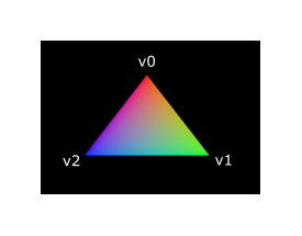
We have to make a couple of changes to both shaders to accomplish this. First off, we need to specify a distinct color for each of the three vertices. The vertex shader should now include an array with colors just like it does for positions:
vec3 colors[3] = vec3[](
    vec3(1.0, 0.0, 0.0),
    vec3(0.0, 1.0, 0.0),
    vec3(0.0, 0.0, 1.0)
);
Now we just need to pass these per-vertex colors to the fragment shader so it can output their interpolated values to the framebuffer. Add an output for color to the vertex shader and write to it in the main function:
layout(location = 0) out vec3 fragColor;

void main() {
    gl_Position = vec4(positions[gl_VertexIndex], 0.0, 1.0);
    fragColor = colors[gl_VertexIndex];
}
Next, we need to add a matching input in the fragment shader:
layout(location = 0) in vec3 fragColor;

void main() {
    outColor = vec4(fragColor, 1.0);
}
The input variable does not necessarily have to use the same name, they will be linked together using the indexes specified by the location directives. The main function has been modified to output the color along with an alpha value. As shown in the image above, the values for fragColor will be automatically interpolated for the fragments between the three vertices, resulting in a smooth gradient.
Compiling the shaders
Create a resources directory adjacent to the java directory under src/main of your project, then create a resources/shader directory and store the vertex shader in a file called shader.vert and the fragment shader in a file called shader.frag in that directory. GLSL shaders don't have an official extension, but these two are commonly used to distinguish them.
The contents of shader.vert should be:
#version 450

layout(location = 0) out vec3 fragColor;

vec2 positions[3] = vec2[](
    vec2(0.0, -0.5),
    vec2(0.5, 0.5),
    vec2(-0.5, 0.5)
);

vec3 colors[3] = vec3[](
    vec3(1.0, 0.0, 0.0),
    vec3(0.0, 1.0, 0.0),
    vec3(0.0, 0.0, 1.0)
);

void main() {
    gl_Position = vec4(positions[gl_VertexIndex], 0.0, 1.0);
    fragColor = colors[gl_VertexIndex];
}
The contents of shader.frag should be:
#version 450

layout(location = 0) in vec3 fragColor;
layout(location = 0) out vec4 outColor;

void main() {
    outColor = vec4(fragColor, 1.0);
}
We're now going to compile these into SPIR-V bytecode using the glslc program.
Windows
Create a compile.bat file with the following contents:
C:/VulkanSDK/x.x.x.x/Bin32/glslc.exe shader.vert -o vert.spv
C:/VulkanSDK/x.x.x.x/Bin32/glslc.exe shader.frag -o frag.spv
pause
Replace the path to glslc.exe with the path to where you installed the Vulkan SDK. Double-click the file to run it.
Linux
Create a compile.sh file with the following contents:
/home/user/VulkanSDK/x.x.x.x/x86_64/bin/glslc shader.vert -o vert.spv
/home/user/VulkanSDK/x.x.x.x/x86_64/bin/glslc shader.frag -o frag.spv
Replace the path to glslc with the path to where you installed the Vulkan SDK. Make the script executable with chmod +x compile.sh and run it.
End of platform-specific instructions
These two commands tell the compiler to read the GLSL source file and output a SPIR-V bytecode file using the -o (output) flag.
If your shader contains a syntax error then the compiler will tell you the line number and problem, as you would expect. Try leaving out a semicolon for example and run the compile script again. Also try running the compiler without any arguments to see what kinds of flags it supports. It can, for example, also output the bytecode into a human-readable format so you can see exactly what your shader is doing and any optimizations that have been applied at this stage.
Compiling shaders on the commandline is one of the most straightforward options and it's the one that we'll use in this tutorial, but it's also possible to compile shaders directly from your own code. The Vulkan SDK includes libshaderc, which is a library to compile GLSL code to SPIR-V from within your program.
Loading a shader
Now that we have a way of producing SPIR-V shaders, it's time to load them into our program to plug them into the graphics pipeline at some point. We'll first write a simple helper function to load the binary data from the files.
private static IntBuffer readShaderFile(String filename, Arena arena) {
    try (var stream = Application.class.getResourceAsStream(filename)) {
        if (stream == null) {
            throw new RuntimeException("Failed to open shader file: " + filename);
        }

        var bytes = stream.readAllBytes();
        assert bytes.length % Integer.BYTES == 0;

        return IntBuffer.allocate(arena, bytes);
    }
    catch (IOException e) {
        throw new RuntimeException("Failed to read shader file: " + filename, e);
    }
}
We're using Java resource system to load the files, which may not be very optimal but sufficient for this tutorial. The function reads the entire file into a byte array and then copies it into an IntBuffer that we can use to create a Vulkan shader module.
We'll now call this function from createGraphicsPipeline to load the bytecode of the two shaders:
private void createGraphicsPipeline() {
    try (var arena = Arena.ofConfined()) {
        var vertShaderCode = readShaderFile("/shader/vert.spv", arena);
        var fragShaderCode = readShaderFile("/shader/frag.spv", arena);
    }
}
Creating shader modules
Before we can pass the code to the pipeline, we have to wrap it in a VkShaderModule object. Let's create a helper function createShaderModule to do that.
private VkShaderModule createShaderModule(IntBuffer code) {
}
The function will take a buffer with the bytecode as parameter and create a VkShaderModule from it.
Creating a shader module is simple, we only need to specify a pointer to the buffer with the bytecode and the length of it. This information is specified in a VkShaderModuleCreateInfo structure. The one catch is that the size of the bytecode is specified in bytes, but the bytecode pointer is a uint32_t pointer rather than a char pointer. And that's why we were using an IntBuffer to store the bytecode.
try (var localArena = Arena.ofConfined()) {
    var createInfo = VkShaderModuleCreateInfo.allocate(localArena);
    createInfo.codeSize(code.size() * Integer.BYTES);
    createInfo.pCode(code);
}
The VkShaderModule can then be created with a call to vkCreateShaderModule:
var pShaderModule = VkShaderModule.Buffer.allocate(localArena);
var result = deviceCommands.vkCreateShaderModule(device, createInfo, null, pShaderModule);
if (result != VkResult.VK_SUCCESS) {
    throw new RuntimeException("Failed to create shader module, vulkan error code: " + VkResult.explain(result));
}
return pShaderModule.read();
The parameters are the same as those in previous object creation functions: the logical device, pointer to create info structure, optional pointer to custom allocators and handle output variable. The buffer with the code can be freed immediately after creating the shader module, but we keep it simple and do not try to optimize this further.
Shader modules are just a thin wrapper around the shader bytecode that we've previously loaded from a file and the functions defined in it. The compilation and linking of the SPIR-V bytecode to machine code for execution by the GPU doesn't happen until the graphics pipeline is created. That means that we're allowed to destroy the shader modules again as soon as pipeline creation is finished, which is why we'll make them local variables in the createGraphicsPipeline function instead of class members:
var vertexShaderModule = createShaderModule(vertShaderCode);
var fragmentShaderModule = createShaderModule(fragShaderCode);
The cleanup should then happen at the end of the function by adding two calls to vkDestroyShaderModule. All the remaining code in this chapter will be inserted before these lines.
// ...

deviceCommands.vkDestroyShaderModule(device, vertexShaderModule, null);
deviceCommands.vkDestroyShaderModule(device, fragmentShaderModule, null);
Shader stage creation
To actually use the shaders we'll need to assign them to a specific pipeline stage through VkPipelineShaderStageCreateInfo structures as part of the actual pipeline creation process.
We'll start by filling in the structure for the vertex shader, again in the createGraphicsPipeline function.
var shaderStages = VkPipelineShaderStageCreateInfo.allocate(arena, 2);

var vertShaderStageInfo = shaderStages[0];
vertShaderStageInfo.stage(VkShaderStageFlags.VK_SHADER_STAGE_VERTEX_BIT);
The first step, is telling Vulkan in which pipeline stage the shader is going to be used. There is an enum value for each of the programmable stages described in the previous chapter.
vertShaderStageInfo.module(vertexShaderModule);
vertShaderStageInfo.pName(ByteBuffer.allocateString(arena, "main"));
The next two members specify the shader module containing the code, and the function to invoke, known as the entrypoint. That means that it's possible to combine multiple fragment shaders into a single shader module and use different entry points to differentiate between their behaviors. In this case we'll stick to the standard main, however.
There is one more (optional) member, pSpecializationInfo, which we won't be using here, but is worth discussing. It allows you to specify values for shader constants. You can use a single shader module where its behavior can be configured at pipeline creation by specifying different values for the constants used in it. This is more efficient than configuring the shader using variables at render time, because the compiler can do optimizations like eliminating if statements that depend on these values. If you don't have any constants like that, then you can set the member to null, which our struct initialization does automatically.
Modifying the structure to suit the fragment shader is easy:
var fragShaderStageInfo = shaderStages[1];
fragShaderStageInfo.stage(VkShaderStageFlags.VK_SHADER_STAGE_FRAGMENT_BIT);
fragShaderStageInfo.module(fragmentShaderModule);
fragShaderStageInfo.pName(ByteBuffer.allocateString(arena, "main"));
That's all there is describing the programmable stages of the pipeline. In the next chapter we'll look at the fixed-function stages.
Fixed functions
The older graphics APIs provided default state for most of the stages of the graphics pipeline. In Vulkan you have to be explicit about most pipeline states as it'll be baked into an immutable pipeline state object. In this chapter we'll fill in all of the structures to configure these fixed-function operations.
Dynamic state
While most of the pipeline state needs to be baked into the pipeline state, a limited amount of the state can actually be changed without recreating the pipeline at draw time. Examples are the size of the viewport, line width and blend constants. If you want to use dynamic state and keep these properties out, then you'll have to fill in a VkPipelineDynamicStateCreateInfo structure like this:
var dynamicStates = IntBuffer.allocate(arena, 2);
dynamicStates.write(0, VkDynamicState.VK_DYNAMIC_STATE_VIEWPORT);
dynamicStates.write(1, VkDynamicState.VK_DYNAMIC_STATE_SCISSOR);

var dynamicStateInfo = VkPipelineDynamicStateCreateInfo.allocate(arena);
dynamicState.dynamicStateCount(2);
dynamicState.pDynamicStates(dynamicStates);
This will cause the configuration of these values to be ignored, and you will be able (and required) to specify the data at drawing time. This results in a more flexible setup and is very common for things like viewport and scissor state, which would result in a more complex setup when being baked into the pipeline state.
Vertex input
The VkPipelineVertexInputStateCreateInfo structure describes the format of the vertex data that will be passed to the vertex shader. It describes this in roughly two ways:
- Bindings: spacing between data and whether the data is per-vertex or per-instance (see instancing)
- Attribute descriptions: type of the attributes passed to the vertex shader, which binding to load them from and at which offset
Because we're hard coding the vertex data directly in the vertex shader, we'll fill in this structure to specify that there is no vertex data to load for now. We'll get back to it in the vertex buffer chapter.
var vertexInputInfo = VkPipelineVertexInputStateCreateInfo.allocate(arena);
// members are automatically zeroed by the arena allocation
Add this structure to the createGraphicsPipeline function right after the shaderStages array.
Input assembly
The VkPipelineInputAssemblyStateCreateInfo struct describes two things: what kind of geometry will be drawn from the vertices and if primitive restart should be enabled. The former is specified in the topology member and can have values like:
VK_PRIMITIVE_TOPOLOGY_POINT_LIST: points from verticesVK_PRIMITIVE_TOPOLOGY_LINE_LIST: line from every 2 vertices without reuseVK_PRIMITIVE_TOPOLOGY_LINE_STRIP: the end vertex of every line is used as start vertex for the next lineVK_PRIMITIVE_TOPOLOGY_TRIANGLE_LIST: triangle from every 3 vertices without reuseVK_PRIMITIVE_TOPOLOGY_TRIANGLE_STRIP: the second and third vertex of every triangle are used as first two vertices of the next triangle
Normally, the vertices are loaded from the vertex buffer by index in sequential order, but with an element buffer you can specify the indices to use yourself. This allows you to perform optimizations like reusing vertices. If you set the primitiveRestartEnable member to VK_TRUE, then it's possible to break up lines and triangles in the _STRIP topology modes by using a special index of 0xFFFF or 0xFFFFFFFF.
We intend to draw triangles throughout this tutorial, so we'll stick to the following data for the structure:
var inputAssembly = VkPipelineInputAssemblyStateCreateInfo.allocate(arena);
inputAssembly.topology(VkPrimitiveTopology.VK_PRIMITIVE_TOPOLOGY_TRIANGLE_LIST);
inputAssembly.primitiveRestartEnable(Constants.VK_FALSE);
Viewports and scissors
A viewport basically describes the region of the framebuffer that the output will be rendered to. This will almost always be (0, 0) to (width, height) and in this tutorial that will also be the case.
var viewport = VkViewport.allocate(arena);
viewport.x(0.0f);
viewport.y(0.0f);
viewport.width(swapChainExtent.width());
viewport.height(swapChainExtent.height());
viewport.minDepth(0.0f);
viewport.maxDepth(1.0f);
Remember that the size of the swap chain and its images may differ from the WIDTH and HEIGHT of the window. The swap chain images will be used as framebuffers later on, so we should stick to their size.
The minDepth and maxDepth values specify the range of depth values to use for the framebuffer. These values must be within the [0.0f, 1.0f] range, but minDepth may be higher than maxDepth. If you aren't doing anything special, then you should stick to the standard values of 0.0f and 1.0f.
While viewports define the transformation from the image to the framebuffer, scissor rectangles define in which regions pixels will actually be stored. Any pixels outside the scissor rectangles will be discarded by the rasterizer. They function like a filter rather than a transformation. The difference is illustrated below. Note that the left scissor rectangle is just one of the many possibilities that would result in that image, as long as it's larger than the viewport.

So if we wanted to draw to the entire framebuffer, we would specify a scissor rectangle that covers it entirely:
var scissor = VkRect2D.allocate(arena);
scissor.offset().x(0);
scissor.offset().y(0);
scissor.extent(swapChainExtent);
Viewport(s) and scissor rectangle(s) can either be specified as a static part of the pipeline or as a dynamic state set in the command buffer. While the former is more in line with the other states it's often convenient to make viewport and scissor state dynamic as it gives you a lot more flexibility. This is very common and all implementations can handle this dynamic state without a performance penalty.
When opting for dynamic viewport(s) and scissor rectangle(s) you need to enable the respective dynamic states for the pipeline:
var dynamicStates = IntBuffer.allocate(arena, 2);
dynamicStates.write(0, VkDynamicState.VK_DYNAMIC_STATE_VIEWPORT);
dynamicStates.write(1, VkDynamicState.VK_DYNAMIC_STATE_SCISSOR);
var dynamicStateInfo = VkPipelineDynamicStateCreateInfo.allocate(arena);
dynamicStateInfo.dynamicStateCount(2);
dynamicStateInfo.pDynamicStates(dynamicStates);
And then you only need to specify their count at pipeline creation time:
var viewportStateInfo = VkPipelineViewportStateCreateInfo.allocate(arena);
viewportStateInfo.viewportCount(1);
viewportStateInfo.scissorCount(1);
The actual viewport(s) and scissor rectangle(s) will then later be set up at drawing time.
With dynamic state it's even possible to specify different viewports and or scissor rectangles within a single command buffer.
Without dynamic state, the viewport and scissor rectangle need to be set in the pipeline using the VkPipelineViewportStateCreateInfo struct. This makes the viewport and scissor rectangle for this pipeline immutable. Any changes required to these values would require a new pipeline to be created with the new values.
var viewportStateInfo = VkPipelineViewportStateCreateInfo.allocate(arena);
viewportStateInfo.viewportCount(1);
viewportStateInfo.pViewports(viewport);
viewportStateInfo.scissorCount(1);
viewportStateInfo.pScissors(scissor);
Independent of how you set them, it is possible to use multiple viewports and scissor rectangles on some graphics cards, so the structure members reference an array of them. Using multiple requires enabling a GPU feature (see logical device creation).
In this tutorial, our following code will assume that the viewport and scissor rectangle are dynamic.
Rasterizer
The rasterizer takes the geometry that is shaped by the vertices from the vertex shader and turns it into fragments to be colored by the fragment shader. It also performs depth testing, face culling and the scissor test, and it can be configured to output fragments that fill entire polygons or just the edges (wireframe rendering). All this is configured using the VkPipelineRasterizationStateCreateInfo structure.
var rasterizer = VkPipelineRasterizationStateCreateInfo.allocate(arena);
rasterizer.depthClampEnable(Constants.VK_FALSE);
If depthClampEnable is set to VK_TRUE, then fragments that are beyond the near and far planes are clamped to them as opposed to discarding them. This is useful in some special cases like shadow maps. Using this requires enabling a GPU feature.
rasterizer.rasterizerDiscardEnable(Constants.VK_FALSE);
If rasterizerDiscardEnable is set to VK_TRUE, then geometry never passes through the rasterizer stage. This basically disables any output to the framebuffer.
rasterizer.polygonMode(VkPolygonMode.VK_POLYGON_MODE_FILL);
The polygonMode determines how fragments are generated for geometry. The following modes are available:
VK_POLYGON_MODE_FILL: fill the area of the polygon with fragmentsVK_POLYGON_MODE_LINE: polygon edges are drawn as linesVK_POLYGON_MODE_POINT: polygon vertices are drawn as points
Using any mode other than fill requires enabling a GPU feature.
rasterizer.lineWidth(1.0f);
The lineWidth member is straightforward, it describes the thickness of lines in terms of number of fragments. The maximum line width that is supported depends on the hardware and any line thicker than 1.0f requires you to enable the wideLines GPU feature.
rasterizer.cullMode(VkCullModeFlags.VK_CULL_MODE_BACK_BIT);
rasterizer.frontFace(VkFrontFace.VK_FRONT_FACE_CLOCKWISE);
The cullMode variable determines the type of face culling to use. You can disable culling, cull the front faces, cull the back faces or both. The frontFace variable specifies the vertex order for faces to be considered front-facing and can be clockwise or counterclockwise.
rasterizer.depthBiasEnable(Constants.VK_FALSE);
rasterizer.depthBiasConstantFactor(0.0f); // optional
rasterizer.depthBiasClamp(0.0f); // optional
rasterizer.depthBiasSlopeFactor(0.0f); // optional
The rasterizer can alter the depth values by adding a constant value or biasing them based on a fragment's slope. This is sometimes used for shadow mapping, but we won't be using it. Just set depthBiasEnable to VK_FALSE.
Multisampling
The VkPipelineMultisampleStateCreateInfo struct configures multisampling, which is one of the ways to perform antialiasing. It works by combining the fragment shader results of multiple polygons that rasterize to the same pixel. This mainly occurs along edges, which is also where the most noticeable aliasing artifacts occur. Because it doesn't need to run the fragment shader multiple times if only one polygon maps to a pixel, it is significantly less expensive than simply rendering to a higher resolution and then downscaling. Enabling it requires enabling a GPU feature.
var multisampling = VkPipelineMultisampleStateCreateInfo.allocate(arena);
multisampling.sampleShadingEnable(Constants.VK_FALSE);
multisampling.rasterizationSamples(VkSampleCountFlags.VK_SAMPLE_COUNT_1_BIT);
multisampling.minSampleShading(1.0f); // Optional
multisampling.pSampleMask(null); // Optional
multisampling.alphaToCoverageEnable(Constants.VK_FALSE); // Optional
multisampling.alphaToOneEnable(Constants.VK_FALSE); // Optional
We'll revisit multisampling in later chapter, for now let's keep it disabled.
Depth and stencil testing
If you are using a depth and/or stencil buffer, then you also need to configure the depth and stencil tests using VkPipelineDepthStencilStateCreateInfo. We don't have one right now, so we can simply pass a null instead of a pointer to such a struct. We'll get back to it in the depth buffering chapter.
Color blending
After a fragment shader has returned a color, it needs to be combined with the color that is already in the framebuffer. This transformation is known as color blending and there are two ways to do it:
- Mix the old and new value to produce a final color
- Combine the old and new value using a bitwise operation
There are two types of structs to configure color blending. The first struct, VkPipelineColorBlendAttachmentState contains the configuration per attached framebuffer and the second struct, VkPipelineColorBlendStateCreateInfo contains the global color blending settings. In our case we only have one framebuffer:
var colorBlendAttachment = VkPipelineColorBlendAttachmentState.allocate(arena);
colorBlendAttachment.colorWriteMask(
        VkColorComponentFlags.VK_COLOR_COMPONENT_R_BIT |
                VkColorComponentFlags.VK_COLOR_COMPONENT_G_BIT |
                VkColorComponentFlags.VK_COLOR_COMPONENT_B_BIT |
                VkColorComponentFlags.VK_COLOR_COMPONENT_A_BIT
);
colorBlendAttachment.blendEnable(Constants.VK_FALSE);
colorBlendAttachment.srcColorBlendFactor(VkBlendFactor.VK_BLEND_FACTOR_ONE); // Optional
colorBlendAttachment.dstColorBlendFactor(VkBlendFactor.VK_BLEND_FACTOR_ZERO); // Optional
colorBlendAttachment.colorBlendOp(VkBlendOp.VK_BLEND_OP_ADD); // Optional
colorBlendAttachment.srcAlphaBlendFactor(VkBlendFactor.VK_BLEND_FACTOR_ONE); // Optional
colorBlendAttachment.dstAlphaBlendFactor(VkBlendFactor.VK_BLEND_FACTOR_ZERO); // Optional
colorBlendAttachment.alphaBlendOp(VkBlendOp.VK_BLEND_OP_ADD); // Optional
This per-framebuffer struct allows you to configure the first way of color blending. The operations that will be performed are best demonstrated using the following pseudocode:
if (blendEnable) {
    finalColor.rgb = (srcColorBlendFactor * newColor.rgb) <colorBlendOp> (dstColorBlendFactor * oldColor.rgb);
    finalColor.a = (srcAlphaBlendFactor * newColor.a) <alphaBlendOp> (dstAlphaBlendFactor * oldColor.a);
} else {
    finalColor = newColor;
}

finalColor = finalColor & colorWriteMask;
If blendEnable is set to VK_FALSE, then the new color from the fragment shader is passed through unmodified. Otherwise, the two mixing operations are performed to compute a new color. The resulting color is AND'd with the colorWriteMask to determine which channels are actually passed through.
The most common way to use color blending is to implement alpha blending, where we want the new color to be blended with the old color based on its opacity. The finalColor should then be computed as follows:
finalColor.rgb = newAlpha * newColor + (1 - newAlpha) * oldColor;
finalColor.a = newAlpha.a;
This can be accomplished with the following parameters:
colorBlendAttachment.blendEnable(Constants.VK_TRUE);
colorBlendAttachment.srcColorBlendFactor(VkBlendFactor.VK_BLEND_FACTOR_SRC_ALPHA);
colorBlendAttachment.dstColorBlendFactor(VkBlendFactor.VK_BLEND_FACTOR_ONE_MINUS_SRC_ALPHA);
colorBlendAttachment.colorBlendOp(VkBlendOp.VK_BLEND_OP_ADD);
colorBlendAttachment.srcAlphaBlendFactor(VkBlendFactor.VK_BLEND_FACTOR_ONE);
colorBlendAttachment.dstAlphaBlendFactor(VkBlendFactor.VK_BLEND_FACTOR_ZERO);
colorBlendAttachment.alphaBlendOp(VkBlendOp.VK_BLEND_OP_ADD);
You can find all the possible operations in the VkBlendFactor and VkBlendOp enumerations in the specification.
The second structure references the array of structures for all the framebuffers and allows you to set blend constants that you can use as blend factors in the aforementioned calculations.
var colorBlending = VkPipelineColorBlendStateCreateInfo.allocate(arena);
colorBlending.logicOpEnable(Constants.VK_FALSE);
colorBlending.logicOp(VkLogicOp.VK_LOGIC_OP_COPY); // Optional
colorBlending.attachmentCount(1);
colorBlending.pAttachments(colorBlendAttachment);
colorBlending.blendConstants().write(0, 0.0f); // Optional
colorBlending.blendConstants().write(1, 0.0f); // Optional
colorBlending.blendConstants().write(2, 0.0f); // Optional
colorBlending.blendConstants().write(3, 0.0f); // Optional
If you want to use the second method of blending (bitwise combination), then you should set logicOpEnable to VK_TRUE. The bitwise operation can then be specified in the logicOp field. Note that this will automatically disable the first method, as if you had set blendEnable to VK_FALSE for every attached framebuffer! The colorWriteMask will also be used in this mode to determine which channels in the framebuffer will actually be affected. It is also possible to disable both modes, as we've done here, in which case the fragment colors will be written to the framebuffer unmodified.
Pipeline layout
You can use uniform values in shaders, which are globals similar to dynamic state variables that can be changed at drawing time to alter the behavior of your shaders without having to recreate them. They are commonly used to pass the transformation matrix to the vertex shader, or to create texture samplers in the fragment shader.
These uniform values need to be specified during pipeline creation by creating a VkPipelineLayout object. Even though we won't be using them until a future chapter, we are still required to create an empty pipeline layout.
Create a class member to hold this object, because we'll refer to it from other functions at a later point in time:
private VkPipelineLayout pipelineLayout;
And then create the object in the createGraphicsPipeline function:
var pipelineLayoutInfo = VkPipelineLayoutCreateInfo.allocate(arena);
pipelineLayoutInfo.setLayoutCount(0); // Optional
pipelineLayoutInfo.pSetLayouts(null); // Optional
pipelineLayoutInfo.pushConstantRangeCount(0); // Optional
pipelineLayoutInfo.pPushConstantRanges(null); // Optional

var pPipelineLayout = VkPipelineLayout.Buffer.allocate(arena);
var result = deviceCommands.vkCreatePipelineLayout(device, pipelineLayoutInfo, null, pPipelineLayout);
if (result != VkResult.VK_SUCCESS) {
    throw new RuntimeException("Failed to create pipeline layout, vulkan error code: " + VkResult.explain(result));
}
pipelineLayout = pPipelineLayout.read();
The structure also specifies push constants, which are another way of passing dynamic values to shaders that we may get into in a future chapter. The pipeline layout will be referenced throughout the program's lifetime, so it should be destroyed at the end:
private void cleanup() {
    deviceCommands.vkDestroyPipelineLayout(device, pipelineLayout, null);
    // ...
}
Conclusion
That's it for all the fixed-function state! It's a lot of work to set all of this up from scratch, but the advantage is that we're now nearly fully aware of everything that is going on in the graphics pipeline! This reduces the chance of running into unexpected behavior because the default state of certain components is not what you expect.
There is however one more object to create before we can finally create the graphics pipeline and that is a render pass.
Render passes
Setup
Before we can finish creating the pipeline, we need to tell Vulkan about the framebuffer attachments that will be used while rendering. We need to specify how many color and depth buffers there will be, how many samples to use for each of them and how their contents should be handled throughout the rendering operations. All of this information is wrapped in a render pass object, for which we'll create a new createRenderPass function. Call this function from initVulkan before createGraphicsPipeline.
private void initVulkan() {
    // ...
    createImageViews();
    createRenderPass();
    createGraphicsPipeline();
}

// ...

private void createRenderPass() {
}
Attachment description
In our case we'll have just a single color buffer attachment represented by one of the images from the swap chain.
private void createRenderPass() {
    try (var arena = Arena.ofConfined()) {
        var colorAttachment = VkAttachmentDescription.allocate(arena);
        colorAttachment.format(swapChainImageFormat);
        colorAttachment.samples(VkSampleCountFlags.VK_SAMPLE_COUNT_1_BIT);
    }
}
The format of the color attachment should match the format of the swap chain images, and we're not doing anything with multisampling yet, so we'll stick to 1 sample.
colorAttachment.loadOp(VkAttachmentLoadOp.VK_ATTACHMENT_LOAD_OP_CLEAR);
colorAttachment.storeOp(VkAttachmentStoreOp.VK_ATTACHMENT_STORE_OP_STORE);
The loadOp and storeOp determine what to do with the data in the attachment before rendering and after rendering. We have the following choices for loadOp:
VK_ATTACHMENT_LOAD_OP_LOAD: Preserve the existing contents of the attachmentVK_ATTACHMENT_LOAD_OP_CLEAR: Clear the values to a constant at the startVK_ATTACHMENT_LOAD_OP_DONT_CARE: Existing contents are undefined; we don't care about them
In our case we're going to use the clear operation to clear the framebuffer to black before drawing a new frame. There are only two possibilities for the storeOp:
VK_ATTACHMENT_STORE_OP_STORE: Rendered contents will be stored in memory and can be read laterVK_ATTACHMENT_STORE_OP_DONT_CARE: Contents of the framebuffer will be undefined after the rendering operation
We're interested in seeing the rendered triangle on the screen, so we're going with the store operation here.
colorAttachment.stencilLoadOp(VkAttachmentLoadOp.VK_ATTACHMENT_LOAD_OP_DONT_CARE);
colorAttachment.stencilStoreOp(VkAttachmentStoreOp.VK_ATTACHMENT_STORE_OP_DONT_CARE);
The loadOp and storeOp apply to color and depth data, and stencilLoadOp / stencilStoreOp apply to stencil data. Our application won't do anything with the stencil buffer, so the results of loading and storing are irrelevant.
colorAttachment.initialLayout(VkImageLayout.VK_IMAGE_LAYOUT_UNDEFINED);
colorAttachment.finalLayout(VkImageLayout.VK_IMAGE_LAYOUT_PRESENT_SRC_KHR);
Textures and framebuffers in Vulkan are represented by VkImage objects with a certain pixel format, however the layout of the pixels in memory can change based on what you're trying to do with an image.
Some of the most common layouts are:
VK_IMAGE_LAYOUT_COLOR_ATTACHMENT_OPTIMAL: Images used as color attachmentVK_IMAGE_LAYOUT_PRESENT_SRC_KHR: Images to be presented in the swap chainVK_IMAGE_LAYOUT_TRANSFER_DST_OPTIMAL: Images to be used as destination for a memory copy operation
We'll discuss this topic in more depth in the texturing chapter, but what's important to know right now is that images need to be transitioned to specific layouts that are suitable for the operation that they're going to be involved in next.
The initialLayout specifies which layout the image will have before the render pass begins. The finalLayout specifies the layout to automatically transition to when the render pass finishes. Using VK_IMAGE_LAYOUT_UNDEFINED for initialLayout means that we don't care what previous layout the image was in. The caveat of this special value is that the contents of the image are not guaranteed to be preserved, but that doesn't matter since we're going to clear it anyway. We want the image to be ready for presentation using the swap chain after rendering, which is why we use VK_IMAGE_LAYOUT_PRESENT_SRC_KHR as finalLayout.
Subpasses and attachment references
A single render pass can consist of multiple subpasses. Subpasses are subsequent rendering operations that depend on the contents of framebuffers in previous passes, for example a sequence of post-processing effects that are applied one after another. If you group these rendering operations into one render pass, then Vulkan is able to reorder the operations and conserve memory bandwidth for possibly better performance. For our very first triangle, however, we'll stick to a single subpass.
Every subpass references one or more of the attachments that we've described using the structure in the previous sections. These references are themselves VkAttachmentReference structs that look like this:
var colorAttachmentRef = VkAttachmentReference.allocate(arena);
colorAttachmentRef.attachment(0);
colorAttachmentRef.layout(VkImageLayout.VK_IMAGE_LAYOUT_COLOR_ATTACHMENT_OPTIMAL);
The attachment parameter specifies which attachment to reference by its index in the attachment descriptions array. Our array consists of a single VkAttachmentDescription, so its index is 0. The layout specifies which layout we would like the attachment to have during a subpass that uses this reference. Vulkan will automatically transition the attachment to this layout when the subpass is started. We intend to use the attachment to function as a color buffer and the VK_IMAGE_LAYOUT_COLOR_ATTACHMENT_OPTIMAL layout will give us the best performance, as its name implies.
The subpass is described using a VkSubpassDescription structure:
var subpass = VkSubpassDescription.allocate(arena);
subpass.pipelineBindPoint(VkPipelineBindPoint.VK_PIPELINE_BIND_POINT_GRAPHICS);
Vulkan may also support compute subpasses in the future, so we have to be explicit about this being a graphics subpass. Next, we specify the reference to the color attachment:
subpass.colorAttachmentCount(1);
subpass.pColorAttachments(colorAttachmentRef);
The index of the attachment in this array is directly referenced from the fragment shader with the layout(location = 0) out vec4 outColor directive!
The following other types of attachments can be referenced by a subpass:
pInputAttachments: Attachments that are read from a shaderpResolveAttachments: Attachments used for multisampling color attachmentspDepthStencilAttachment: Attachment for depth and stencil datapPreserveAttachments: Attachments that are not used by this subpass, but for which the data must be preserved
Render pass
Now that the attachment and a basic subpass referencing it have been described, we can create the render pass itself. Create a new class member variable to hold the VkRenderPass object right above the pipelineLayout variable:
private VkRenderPass renderPass;
private VkPipelineLayout pipelineLayout;
The render pass object can then be created by filling in the VkRenderPassCreateInfo structure with an array of attachments and subpasses. The VkAttachmentReference objects reference attachments using the indices of this array.
var renderPassInfo = VkRenderPassCreateInfo.allocate(arena);
renderPassInfo.attachmentCount(1);
renderPassInfo.pAttachments(colorAttachment);
renderPassInfo.subpassCount(1);
renderPassInfo.pSubpasses(subpass);

var pRenderPass = VkRenderPass.Buffer.allocate(arena);
var result = deviceCommands.vkCreateRenderPass(device, renderPassInfo, null, pRenderPass);
if (result != VkResult.VK_SUCCESS) {
    throw new RuntimeException("Failed to create render pass, vulkan error code: " + VkResult.explain(result));
}
renderPass = pRenderPass.read();
Just like the pipeline layout, the render pass will be referenced throughout the program, so it should only be cleaned up at the end:
private void cleanup() {
    deviceCommands.vkDestroyPipelineLayout(device, pipelineLayout, null);
    deviceCommands.vkDestroyRenderPass(device, renderPass, null);
    // ...
}
That was a lot of work, but in the next chapter it all comes together to finally create the graphics pipeline object!
Conclusion
We can now combine all the structures and objects from the previous chapters to create the graphics pipeline! Here's the types of objects we have now, as a quick recap:
- Shader stages: the shader modules that define the functionality of the programmable stages of the graphics pipeline
- Fixed-function state: all the structures that define the fixed-function stages of the pipeline, like input assembly, rasterizer, viewport and color blending
- Pipeline layout: the uniform and push values referenced by the shader that can be updated at draw time
- Render pass: the attachments referenced by the pipeline stages and their usage
All of these combined fully define the functionality of the graphics pipeline, so we can now begin filling in the VkGraphicsPipelineCreateInfo structure at the end of the createGraphicsPipeline function. But before the calls to vkDestroyShaderModule because these are still to be used during the creation.
var pipelineInfo = VkGraphicsPipelineCreateInfo.allocate(arena);
pipelineInfo.stageCount(2);
pipelineInfo.pStages(shaderStages[0]);
We start by referencing the array of VkPipelineShaderStageCreateInfo structs.
pipelineInfo.pVertexInputState(vertexInputInfo);
pipelineInfo.pInputAssemblyState(inputAssembly);
pipelineInfo.pViewportState(viewportStateInfo);
pipelineInfo.pRasterizationState(rasterizer);
pipelineInfo.pMultisampleState(multisampling);
pipelineInfo.pDepthStencilState(null); // Optional
pipelineInfo.pColorBlendState(colorBlending);
pipelineInfo.pDynamicState(dynamicStateInfo);
Then we reference all the structures describing the fixed-function stage.
pipelineInfo.layout(pipelineLayout);
After that comes the pipeline layout, which is a Vulkan handle rather than a struct pointer.
pipelineInfo.renderPass(renderPass);
pipelineInfo.subpass(0);
And finally we have the reference to the render pass and the index of the sub pass where this graphics pipeline will be used. It is also possible to use other render passes with this pipeline instead of this specific instance, but they have to be compatible with renderPass. The requirements for compatibility are described here, but we won't be using that feature in this tutorial.
pipelineInfo.basePipelineHandle(null); // Optional
pipelineInfo.basePipelineIndex(-1); // Optional
There are actually two more parameters: basePipelineHandle and basePipelineIndex. Vulkan allows you to create a new graphics pipeline by deriving from an existing pipeline. The idea of pipeline derivatives is that it is less expensive to set up pipelines when they have much functionality in common with an existing pipeline and switching between pipelines from the same parent can also be done quicker. You can either specify the handle of an existing pipeline with basePipelineHandle or reference another pipeline that is about to be created by index with basePipelineIndex. Right now there is only a single pipeline, so we'll simply specify a null handle and an invalid index. These values are only used if the VK_PIPELINE_CREATE_DERIVATIVE_BIT flag is also specified in the flags field of VkGraphicsPipelineCreateInfo.
Now prepare for the final step by creating a class member to hold the VkPipeline object:
private VkPipeline graphicsPipeline;
And finally create the graphics pipeline:
var pGraphicsPipeline = VkPipeline.Buffer.allocate(arena);
result = deviceCommands.vkCreateGraphicsPipelines(device, null, 1, pipelineInfo, null, pGraphicsPipeline);
if (result != VkResult.VK_SUCCESS) {
    throw new RuntimeException("Failed to create graphics pipeline, vulkan error code: " + VkResult.explain(result));
}
graphicsPipeline = pGraphicsPipeline.read();
The vkCreateGraphicsPipelines function actually has more parameters than the usual object creation functions in Vulkan. It is designed to take multiple VkGraphicsPipelineCreateInfo objects and create multiple VkPipeline objects in a single call.
The second parameter, for which we've passed the null argument, references an optional VkPipelineCache object. A pipeline cache can be used to store and reuse data relevant to pipeline creation across multiple calls to vkCreateGraphicsPipelines and even across program executions if the cache is stored to a file. This makes it possible to significantly speed up pipeline creation at a later time. We'll get into this in the pipeline cache chapter.
The graphics pipeline is required for all common drawing operations, so it should also only be destroyed at the end of the program:
private void cleanup() {
    deviceCommands.vkDestroyPipeline(device, graphicsPipeline, null);
    // ...
}
Now run your program to confirm that all this hard work has resulted in a successful pipeline creation! We are already getting quite close to seeing something pop up on the screen. In the next couple of chapters we'll set up the actual framebuffers from the swap chain images and prepare the drawing commands.
Framebuffers
We've talked a lot about framebuffers in the past few chapters, and we've set up the render pass to expect a single framebuffer with the same format as the swap chain images, but we haven't actually created any yet.
The attachments specified during render pass creation are bound by wrapping them into a VkFramebuffer object. A framebuffer object references all the VkImageView objects that represent the attachments. In our case that will be only a single one: the color attachment. However, the image that we have to use for the attachment depends on which image the swap chain returns when we retrieve one for presentation. That means that we have to create a framebuffer for all the images in the swap chain and use the one that corresponds to the retrieved image at drawing time.
To that end, create another array class member to hold all the framebuffers:
private VkFramebuffer[] swapChainFramebuffers;
We'll create the objects for this array in a new function createFramebuffers that is called from initVulkan right after creating the graphics pipeline:
private void initVulkan() {
    // ...
    createFramebuffers();
}

// ...

private void createFramebuffers() {
}
Start by creating a Java array to hold the framebuffers:
private void createFramebuffers() {
    swapChainFramebuffers = new VkFramebuffer[swapChainImageViews.length];
}
We'll then iterate through the image views and create framebuffers from them:
for (int i = 0; i < swapChainImageViews.length; i++) {
    try (var arena = Arena.ofConfined()) {
        var pAttachments = VkImageView.Buffer.allocate(arena);
        pAttachments.write(0, swapChainImageViews[i]);

        var framebufferInfo = VkFramebufferCreateInfo.allocate(arena);
        framebufferInfo.renderPass(renderPass);
        framebufferInfo.attachmentCount(1);
        framebufferInfo.pAttachments(pAttachments);
        framebufferInfo.width(swapChainExtent.width());
        framebufferInfo.height(swapChainExtent.height());
        framebufferInfo.layers(1);

        var pFramebuffer = VkFramebuffer.Buffer.allocate(arena);
        var result = deviceCommands.vkCreateFramebuffer(device, framebufferInfo, null, pFramebuffer);
        if (result != VkResult.VK_SUCCESS) {
            throw new RuntimeException("Failed to create framebuffer, vulkan error code: " + VkResult.explain(result));
        }
        swapChainFramebuffers[i] = pFramebuffer.read();
    }
}
As you can see, creation of framebuffers is quite straightforward. We first need to specify with which renderPass the framebuffer needs to be compatible. You can only use a framebuffer with the render passes that it is compatible with, which roughly means that they use the same number and type of attachments.
The attachmentCount and pAttachments parameters specify the VkImageView objects that should be bound to the respective attachment descriptions in the render pass pAttachment array.
The width and height parameters are self-explanatory and layers refers to the number of layers in image arrays. Our swap chain images are single images, so the number of layers is 1.
We should delete the framebuffers before the image views and render pass that they are based on, but only after we've finished rendering:
private void clenaup() {
    for (var framebuffer : swapChainFramebuffers) {
        deviceCommands.vkDestroyFramebuffer(device, framebuffer, null);
    }

    // ...
}
We've now reached the milestone where we have all of the objects that are required for rendering. In the next chapter we're going to write the first actual drawing commands.
Command buffers
Commands in Vulkan, like drawing operations and memory transfers, are not executed directly using function calls. You have to record all the operations you want to perform in command buffer objects. The advantage of this is that when we are ready to tell the Vulkan what we want to do, all the commands are submitted together and Vulkan can more efficiently process the commands since all of them are available together. In addition, this allows command recording to happen in multiple threads if so desired.
Command pools
We have to create a command pool before we can create command buffers. Command pools manage the memory that is used to store the buffers and command buffers are allocated from them. Add a new class member to store a VkCommandPool:
private VkCommandPool commandPool;
Then create a new function createCommandPool and call it from initVulkan after the framebuffers were created.
private void initVulkan() {
    // ...
    createCommandPool();
}

// ...

private void createCommandPool() {
}
Command pool creation only takes two parameters:
private void createCommandPool() {
    try (var arena = Arena.ofConfined()) {
        var queueFamilyIndices = findQueueFamilies(physicalDevice);
        assert queueFamilyIndices != null;

        var poolInfo = VkCommandPoolCreateInfo.allocate(arena);
        poolInfo.flags(VkCommandPoolCreateFlags.VK_COMMAND_POOL_CREATE_RESET_COMMAND_BUFFER_BIT);
        poolInfo.queueFamilyIndex(queueFamilyIndices.graphicsFamily());
    }
}
There are two possible flags for command pools:
VK_COMMAND_POOL_CREATE_TRANSIENT_BIT: Hint that command buffers are rerecorded with new commands very often (may change memory allocation behavior)VK_COMMAND_POOL_CREATE_RESET_COMMAND_BUFFER_BIT: Allow command buffers to be rerecorded individually, without this flag they all have to be reset together
We will be recording a command buffer every frame, so we want to be able to reset and rerecord over it. Thus, we need to set the VK_COMMAND_POOL_CREATE_RESET_COMMAND_BUFFER_BIT flag bit for our command pool.
Command buffers are executed by submitting them on one of the device queues, like the graphics and presentation queues we retrieved. Each command pool can only allocate command buffers that are submitted on a single type of queue. We're going to record commands for drawing, which is why we've chosen the graphics queue family.
var pCommandPool = VkCommandPool.Buffer.allocate(arena);
var result = deviceCommands.vkCreateCommandPool(device, poolInfo, null, pCommandPool);
if (result != VkResult.VK_SUCCESS) {
    throw new RuntimeException("Failed to create command pool, vulkan error code: " + VkResult.explain(result));
}
commandPool = pCommandPool.read();
Finish creating the command pool using the vkCreateCommandPool function. It doesn't have any special parameters. Commands will be used throughout the program to draw things on the screen, so the pool should only be destroyed at the end:
private void cleanup() {
    deviceCommands.vkDestroyCommandPool(device, commandPool, null);
    // ...
}
Command buffer allocation
We can now start allocating command buffers
Create a VkCommandBuffer object as a class member. Command buffers will be automatically freed when their command pool is destroyed, so we don't need explicit cleanup.
private VkCommandBuffer commandBuffer;
We'll now start working on a createCommandBuffer function to allocate a single command buffer from the command pool.
private void initVulkan() {
    // ...
    createCommandBuffer();
}

// ...

private void createCommandBuffer() {
}
Command buffers are allocated with the vkAllocateCommandBuffers function, which takes a VkCommandBufferAllocateInfo struct as parameter that specifies the command pool and number of buffers to allocate:
try (var arena = Arena.ofConfined()) {
    var allocInfo = VkCommandBufferAllocateInfo.allocate(arena);
    allocInfo.commandPool(commandPool);
    allocInfo.level(VkCommandBufferLevel.VK_COMMAND_BUFFER_LEVEL_PRIMARY);
    allocInfo.commandBufferCount(1);

    var pCommandBuffer = VkCommandBuffer.Buffer.allocate(arena);
    var result = deviceCommands.vkAllocateCommandBuffers(device, allocInfo, pCommandBuffer);
    if (result != VkResult.VK_SUCCESS) {
        throw new RuntimeException("Failed to allocate command buffer, vulkan error code: " + VkResult.explain(result));
    }
    commandBuffer = pCommandBuffer.read();
}
The level parameter specifies if the allocated command buffers are primary or secondary command buffers.
VK_COMMAND_BUFFER_LEVEL_PRIMARY: Can be submitted to a queue for execution, but cannot be called from other command buffers.VK_COMMAND_BUFFER_LEVEL_SECONDARY: Cannot be submitted directly, but can be called from primary command buffers.
We won't make use of the secondary command buffer functionality here, but you can imagine that it's helpful to reuse common operations from primary command buffers.
Since we are only allocating one command buffer, the commandBufferCount parameter is just one.
Command buffer recording
We'll now start working on the recordCommandBuffer function that writes the commands we want to execute into a command buffer. The VkCommandBuffer used will be passed in as a parameter, as well as the index of the current swapchain image we want to write to.
private void recordCommandBuffer(VkCommandBuffer commandBuffer, int imageIndex) {
}
We always begin recording a command buffer by calling vkBeginCommandBuffer with a small VkCommandBufferBeginInfo structure as argument that specifies some details about the usage of this specific command buffer.
try (var arena = Arena.ofConfined()) {
    var beginInfo = VkCommandBufferBeginInfo.allocate(arena);
    beginInfo.flags(0); // Optional
    beginInfo.pInheritanceInfo(null); // Optional

    var result = deviceCommands.vkBeginCommandBuffer(commandBuffer, beginInfo);
    if (result != VkResult.VK_SUCCESS) {
        throw new RuntimeException("Failed to begin recording command buffer, vulkan error code: " + VkResult.explain(result));
    }
}
The flags parameter specifies how we're going to use the command buffer. The following values are available:
VK_COMMAND_BUFFER_USAGE_ONE_TIME_SUBMIT_BIT: The command buffer will be rerecorded right after executing it once.VK_COMMAND_BUFFER_USAGE_RENDER_PASS_CONTINUE_BIT: This is a secondary command buffer that will be entirely within a single render pass.VK_COMMAND_BUFFER_USAGE_SIMULTANEOUS_USE_BIT: The command buffer can be resubmitted while it is also already pending execution.
None of these flags are applicable for us right now.
The pInheritanceInfo parameter is only relevant for secondary command buffers. It specifies which state to inherit from the calling primary command buffers.
If the command buffer was already recorded once, then a call to vkBeginCommandBuffer will implicitly reset it. It's not possible to append commands to a buffer at a later time.
Starting a render pass
Drawing starts by beginning the render pass with vkCmdBeginRenderPass. The render pass is configured using some parameters in a VkRenderPassBeginInfo struct.
var renderPassInfo = VkRenderPassBeginInfo.allocate(arena);
renderPassInfo.renderPass(renderPass);
renderPassInfo.framebuffer(swapChainFramebuffers[imageIndex]);
The first two fields are the render pass itself and the attachments to bind. We created a framebuffer for each swap chain image where it is specified as a color attachment. Thus we need to bind the framebuffer for the swapchain image we want to draw to. Using the imageIndex parameter which was passed in, we can pick the right framebuffer for the current swapchain image.
renderPassInfo.renderArea().offset().x(0);
renderPassInfo.renderArea().offset().y(0);
renderPassInfo.renderArea().extent(swapChainExtent);
The next two fields define the size of the render area. The render area defines where shader loads and stores will take place. The pixels outside this region will have undefined values. It should match the size of the attachments for best performance.
renderPassInfo.clearValueCount(1);
var pClearValue = VkClearValue.allocate(arena);
pClearValue.color().float32().write(0, 0.0f);
pClearValue.color().float32().write(1, 0.0f);
pClearValue.color().float32().write(2, 0.0f);
pClearValue.color().float32().write(3, 1.0f);
renderPassInfo.pClearValues(pClearValue);
The last two parameters define the clear values to use for VK_ATTACHMENT_LOAD_OP_CLEAR, which we used as load operation for the color attachment. I've defined the clear color to simply be black with 100% opacity.
deviceCommands.vkCmdBeginRenderPass(commandBuffer, renderPassInfo, VkSubpassContents.VK_SUBPASS_CONTENTS_INLINE);
The render pass can now begin. All the functions that record commands can be recognized by their vkCmd prefix. They all return void, so there will be no error handling until we've finished recording.
The first parameter for every command is always the command buffer to record the command to. The second parameter specifies the details of the render pass we've just provided. The final parameter controls how the drawing commands within the render pass will be provided. It can have one of two values:
VK_SUBPASS_CONTENTS_INLINE: The render pass commands will be embedded in the primary command buffer itself and no secondary command buffers will be executed.VK_SUBPASS_CONTENTS_SECONDARY_COMMAND_BUFFERS: The render pass commands will be executed from secondary command buffers.
We will not be using secondary command buffers, so we'll go with the first option.
Basic drawing commands
We can now bind the graphics pipeline:
deviceCommands.vkCmdBindPipeline(commandBuffer, VkPipelineBindPoint.VK_PIPELINE_BIND_POINT_GRAPHICS, graphicsPipeline);
The second parameter specifies if the pipeline object is a graphics or compute pipeline. We've now told Vulkan which operations to execute in the graphics pipeline and which attachment to use in the fragment shader.
As noted in the fixed functions chapter, we did specify viewport and scissor state for this pipeline to be dynamic. So we need to set them in the command buffer before issuing our draw command:
var viewport = VkViewport.allocate(arena);
viewport.x(0.0f);
viewport.y(0.0f);
viewport.width(swapChainExtent.width());
viewport.height(swapChainExtent.height());
viewport.minDepth(0.0f);
viewport.maxDepth(1.0f);
deviceCommands.vkCmdSetViewport(commandBuffer, 0, 1, viewport);

var scissor = VkRect2D.allocate(arena);
scissor.offset().x(0);
scissor.offset().y(0);
scissor.extent(swapChainExtent);
deviceCommands.vkCmdSetScissor(commandBuffer, 0, 1, scissor);
Now we are ready to issue the draw command for the triangle:
deviceCommands.vkCmdDraw(commandBuffer, 3, 1, 0, 0);
The actual vkCmdDraw function is a bit anticlimactic, but it's so simple because of all the information we specified in advance. It has the following parameters, aside from the command buffer:
vertexCount: Even though we don't have a vertex buffer, we technically still have 3 vertices to draw.instanceCount: Used for instanced rendering, use1if you're not doing that.firstVertex: Used as an offset into the vertex buffer, defines the lowest value ofgl_VertexIndex.firstInstance: Used as an offset for instanced rendering, defines the lowest value ofgl_InstanceIndex.
Finishing up
The render pass can now be ended:
deviceCommands.vkCmdEndRenderPass(commandBuffer);
And we've finished recording the command buffer:
result = deviceCommands.vkEndCommandBuffer(commandBuffer);
if (result != VkResult.VK_SUCCESS) {
    throw new RuntimeException("Failed to end recording command buffer, vulkan error code: " + VkResult.explain(result));
}
In the next chapter we'll write the code for the main loop, which will acquire an image from the swap chain, record and execute a command buffer, then return the finished image to the swap chain.
Rendering and presentation
This is the chapter where everything is going to come together. We're going to write the drawFrame function that will be called from the main loop to put the triangle on the screen. Let's start by creating the function and call it from mainLoop:
private void mainLoop() {
    while (!glfw.glfwWindowShouldClose(window)) {
        glfw.glfwPollEvents();
        drawFrame();
    }
}

// ...

private void drawFrame() {
}
Outline of a frame
At a high level, rendering a frame in Vulkan consists of a common set of steps:
- Wait for the previous frame to finish
- Acquire an image from the swap chain
- Record a command buffer which draws the scene onto that image
- Submit the recorded command buffer
- Present the swap chain image
While we will expand the drawing function in later chapters, for now this is the core of our render loop.
Synchronization
A core design philosophy in Vulkan is that synchronization of execution on the GPU is explicit. The order of operations is up to us to define using various synchronization primitives which tell the driver the order we want things to run in. This means that many Vulkan API calls which start executing work on the GPU are asynchronous, the functions will return before the operation has finished.
In this chapter there are a number of events that we need to order explicitly because they happen on the GPU, such as:
- Acquire an image from the swap chain
- Execute commands that draw onto the acquired image
- Present that image to the screen for presentation, returning it to the swapchain
Each of these events is set in motion using a single function call, but are all executed asynchronously. The function calls will return before the operations are actually finished and the order of execution is also undefined. That is unfortunate, because each of the operations depends on the previous one finishing. Thus we need to explore which primitives we can use to achieve the desired ordering.
Semaphores
A semaphore is used to add order between queue operations. Queue operations refer to the work we submit to a queue, either in a command buffer or from within a function as we will see later. Examples of queues are the graphics queue and the presentation queue. Semaphores are used both to order work inside the same queue and between different queues.
There happens to be two kinds of semaphores in Vulkan, binary and timeline. Because only binary semaphores will be used in this tutorial, we will not discuss timeline semaphores. Further mention of the term semaphore exclusively refers to binary semaphores.
A semaphore is either unsignaled or signaled. It begins life as unsignaled. The way we use a semaphore to order queue operations is by providing the same semaphore as a 'signal' semaphore in one queue operation and as a 'wait' semaphore in another queue operation. For example, lets say we have semaphore S and queue operations A and B that we want to execute in order. What we tell Vulkan is that operation A will 'signal' semaphore S when it finishes executing, and operation B will 'wait' on semaphore S before it begins executing. When operation A finishes, semaphore S will be signaled, while operation B won't start until S is signaled. After operation B begins executing, semaphore S is automatically reset back to being unsignaled, allowing it to be used again.
Pseudocode of what was just described:
VkCommandBuffer A, B = ... // record command buffers
VkSemaphore S = ... // create a semaphore

// enqueue A, signal S when done - starts executing immediately
vkQueueSubmit(work: A, signal: S, wait: None)

// enqueue B, wait on S to start
vkQueueSubmit(work: B, signal: None, wait: S)
Note that in this code snippet, both calls to vkQueueSubmit() return immediately - the waiting only happens on the GPU. The CPU continues running without blocking. To make the CPU wait, we need a different synchronization primitive, which we will now describe.
Fences
A fence has a similar purpose, in that it is used to synchronize execution, but it is for ordering the execution on the CPU, otherwise known as the host. Simply put, if the host needs to know when the GPU has finished something, we use a fence.
Similar to semaphores, fences are either in a signaled or unsignaled state. Whenever we submit work to execute, we can attach a fence to that work. When the work is finished, the fence will be signaled. Then we can make the host wait for the fence to be signaled, guaranteeing that the work has finished before the host continues.
A concrete example is taking a screenshot. Say we have already done the necessary work on the GPU. Now need to transfer the image from the GPU over to the host and then save the memory to a file. We have command buffer A which executes the transfer and fence F. We submit command buffer A with fence F, then immediately tell the host to wait for F to signal. This causes the host to block until command buffer A finishes execution. Thus we are safe to let the host save the file to disk, as the memory transfer has completed.
Pseudocode for what was described:
VkCommandBuffer A = ... // record command buffer with the transfer
VkFence F = ... // create the fence

// enqueue A, start work immediately, signal F when done
vkQueueSubmit(work: A, fence: F)

vkWaitForFence(F) // blocks execution until A has finished executing

save_screenshot_to_disk() // can't run until the transfer has finished
Unlike the semaphore example, this example does block host execution. This means the host won't do anything except wait until execution has finished. For this case, we had to make sure the transfer was complete before we could save the screenshot to disk.
In general, it is preferable to not block the host unless necessary. We want to feed the GPU and the host with useful work to do. Waiting on fences to signal is not useful work. Thus we prefer semaphores, or other synchronization primitives not yet covered, to synchronize our work.
Fences must be reset manually to put them back into the unsignaled state. This is because fences are used to control the execution of the host, and so the host gets to decide when to reset the fence. Contrast this to semaphores which are used to order work on the GPU without the host being involved.
In summary, semaphores are used to specify the execution order of operations on the GPU while fences are used to keep the CPU and GPU in sync with each-other.
What to choose?
We have two synchronization primitives to use and conveniently two places to apply synchronization: Swapchain operations and waiting for the previous frame to finish. We want to use semaphores for swapchain operations because they happen on the GPU, thus we don't want to make the host wait around if we can help it. For waiting on the previous frame to finish, we want to use fences for the opposite reason, because we need the host to wait. This is so we don't draw more than one frame at a time. Because we re-record the command buffer every frame, we cannot record the next frame's work to the command buffer until the current frame has finished executing, as we don't want to overwrite the current contents of the command buffer while the GPU is using it.
Creating the synchronization objects
We'll need one semaphore to signal that an image has been acquired from the swapchain and is ready for rendering, another one to signal that rendering has finished and presentation can happen, and a fence to make sure only one frame is rendering at a time.
Create three class members to store these semaphore objects and fence object:
private VkSemaphore imageAvailableSemaphore;
private VkSemaphore renderFinishedSemaphore;
private VkFence inFlightFence;
To create the semaphores, we'll add the last create function for this part of the tutorial: createSyncObjects:
private void initVulkan() {
    // ...
    createSyncObjects();
}

// ...

private void createSyncObjects() {
}
Creating semaphores requires filling in the VkSemaphoreCreateInfo, but in the current version of the API it doesn't actually have any required fields besides sType (which vulkan4j wrapper initializes automatically for us):
try (var arena = Arena.ofConfined()) {
    var semaphoreInfo = VkSemaphoreCreateInfo.allocate(arena);
}
Future versions of the Vulkan API or extensions may add functionality for the flags and pNext parameters like it does for the other structures.
Creating a fence requires filling in the VkFenceCreateInfo:
var fenceCreateInfo = VkFenceCreateInfo.allocate(arena);
Creating the semaphores and fence follows the familiar pattern with vkCreateSemaphore & vkCreateFence:
var pImageAvailableSemaphore = VkSemaphore.Buffer.allocate(arena);
var pRenderFinishedSemaphore = VkSemaphore.Buffer.allocate(arena);
var pInFlightFence = VkFence.Buffer.allocate(arena);

if (deviceCommands.vkCreateSemaphore(device, semaphoreInfo, null, pImageAvailableSemaphore) != VkResult.VK_SUCCESS ||
        deviceCommands.vkCreateSemaphore(device, semaphoreInfo, null, pRenderFinishedSemaphore) != VkResult.VK_SUCCESS ||
        deviceCommands.vkCreateFence(device, fenceCreateInfo, null, pInFlightFence) != VkResult.VK_SUCCESS) {
    throw new RuntimeException("Failed to create synchronization objects for a frame");
}

imageAvailableSemaphore = pImageAvailableSemaphore.read();
renderFinishedSemaphore = pRenderFinishedSemaphore.read();
inFlightFence = pInFlightFence.read();
The semaphores and fence should be cleaned up at the end of the program, when all commands have finished and no more synchronization is necessary:
private void cleanup() {
    deviceCommands.vkDestroySemaphore(device, imageAvailableSemaphore, null);
    deviceCommands.vkDestroySemaphore(device, renderFinishedSemaphore, null);
    deviceCommands.vkDestroyFence(device, inFlightFence, null);
    // ...
}
Onto the main drawing function!
Waiting for the previous frame
At the start of the frame, we want to wait until the previous frame has finished, so that the command buffer and semaphores are available to use. To do that, we call vkWaitForFences:
deviceCommands.vkWaitForFences(device, 1, pInFlightFences, Constants.VK_TRUE, NativeLayout.UINT64_MAX);
The vkWaitForFences function takes an array of fences and waits on the host for either any or all of the fences to be signaled before returning. The VK_TRUE we pass here indicates that we want to wait for all fences, but in the case of a single one it doesn't matter. This function also has a timeout parameter that we set to the maximum value of a 64bit unsigned integer, UINT64_MAX, which effectively disables the timeout.
After waiting, we need to manually reset the fence to the unsignaled state with the vkResetFences call:
deviceCommands.vkResetFences(device, 1, pInFlightFences);
Before we can proceed, there is a slight hiccup in our design. On the first frame we call drawFrame(), which immediately waits on inFlightFence to be signaled. inFlightFence is only signaled after a frame has finished rendering, yet since this is the first frame, there are no previous frames in which to signal the fence! Thus vkWaitForFences() blocks indefinitely, waiting on something which will never happen.
Of the many solutions to this dilemma, there is a clever workaround built into the API. Create the fence in the signaled state, so that the first call to vkWaitForFences() returns immediately since the fence is already signaled.
To do this, we add the VK_FENCE_CREATE_SIGNALED_BIT flag to the VkFenceCreateInfo:
private void createSyncObjects() {
    // ...

    var fenceCreateInfo = VkFenceCreateInfo.allocate(arena);
    fenceCreateInfo.flags(VkFenceCreateFlags.VK_FENCE_CREATE_SIGNALED_BIT);

    // ...
}
Acquiring an image from the swap chain
The next thing we need to do in the drawFrame function is acquire an image from the swap chain. Recall that the swap chain is an extension feature, so we must use a function with the vk*KHR naming convention:
var pImageIndex = IntBuffer.allocate(arena);
deviceCommands.vkAcquireNextImageKHR(
        device,
        swapChain,
        NativeLayout.UINT64_MAX,
        imageAvailableSemaphore,
        null,
        pImageIndex
);
var imageIndex = pImageIndex.read();
The next two parameters specify synchronization objects that are to be signaled when the presentation engine is finished using the image. That's the point in time where we can start drawing to it. It is possible to specify a semaphore, fence or both. We're going to use our imageAvailableSemaphore for that purpose here.
The last parameter specifies a variable to output the index of the swap chain image that has become available. The index refers to the VkImage in our swapChainImages array. We're going to use that index to pick the VkFrameBuffer.
Recording the command buffer
With the imageIndex specifying the swap chain image to use in hand, we can now record the command buffer. First, we call vkResetCommandBuffer on the command buffer to make sure it is able to be recorded.
deviceCommands.vkResetCommandBuffer(commandBuffer, 0);
The second parameter of vkResetCommandBuffer is a VkCommandBufferResetFlags flag. Since we don't want to do anything special, we leave it as 0.
Now call the function recordCommandBuffer to record the commands we want.
recordCommandBuffer(commandBuffer, imageIndex);
With a fully recorded command buffer, we can now submit it.
Submitting the command buffer
Queue submission and synchronization is configured through parameters in the VkSubmitInfo structure.
var submitInfo = VkSubmitInfo.allocate(arena);
var pWaitSemaphores = VkSemaphore.Buffer.allocate(arena);
pWaitSemaphores.write(imageAvailableSemaphore);
var pWaitStages = IntBuffer.allocate(arena);
pWaitStages.write(VkPipelineStageFlags.VK_PIPELINE_STAGE_COLOR_ATTACHMENT_OUTPUT_BIT);
submitInfo.waitSemaphoreCount(1);
submitInfo.pWaitSemaphores(pWaitSemaphores);
submitInfo.pWaitDstStageMask(pWaitStages);
The first three fields specify which semaphores to wait on before execution begins and in which stage(s) of the pipeline to wait. We want to wait with writing colors to the image until it's available, so we're specifying the stage of the graphics pipeline that writes to the color attachment. That means that theoretically the implementation can already start executing our vertex shader and such while the image is not yet available. Each entry in the waitStages array corresponds to the semaphore with the same index in pWaitSemaphores.
var pCommandBuffers = VkCommandBuffer.Buffer.allocate(arena);
pCommandBuffers.write(commandBuffer);
submitInfo.commandBufferCount(1);
submitInfo.pCommandBuffers(pCommandBuffers);
The next two fields specify which command buffers to actually submit for execution. We simply submit the single command buffer we have.
var pSignalSemaphores = VkSemaphore.Buffer.allocate(arena);
pSignalSemaphores.write(renderFinishedSemaphore);
submitInfo.signalSemaphoreCount(1);
submitInfo.pSignalSemaphores(pSignalSemaphores);
The signalSemaphoreCount and pSignalSemaphores parameters specify which semaphores to signal once the command buffer(s) have finished execution. In our case we're using the renderFinishedSemaphore for that purpose.
var result = deviceCommands.vkQueueSubmit(graphicsQueue, 1, submitInfo, inFlightFence);
if (result != VkResult.VK_SUCCESS) {
    throw new RuntimeException("Failed to submit draw command buffer, vulkan error code: " + VkResult.explain(result));
}
We can now submit the command buffer to the graphics queue using vkQueueSubmit. The function takes an array of VkSubmitInfo structures as argument for efficiency when the workload is much larger. The last parameter references an optional fence that will be signaled when the command buffers finish execution. This allows us to know when it is safe for the command buffer to be reused, thus we want to give it inFlightFence. Now on the next frame, the CPU will wait for this command buffer to finish executing before it records new commands into it.
Subpass dependencies
Remember that the subpasses in a render pass automatically take care of image layout transitions. These transitions are controlled by subpass dependencies, which specify memory and execution dependencies between subpasses. We have only a single subpass right now, but the operations right before and right after this subpass also count as implicit "subpasses".
There are two built-in dependencies that take care of the transition at the start of the render pass and at the end of the render pass, but the former does not occur at the right time. It assumes that the transition occurs at the start of the pipeline, but we haven't acquired the image yet at that point! There are two ways to deal with this problem. We could change the waitStages for the imageAvailableSemaphore to VK_PIPELINE_STAGE_TOP_OF_PIPE_BIT to ensure that the render passes don't begin until the image is available, or we can make the render pass wait for the VK_PIPELINE_STAGE_COLOR_ATTACHMENT_OUTPUT_BIT stage. I've decided to go with the second option here, because it's a good excuse to have a look at subpass dependencies and how they work.
Subpass dependencies are specified in VkSubpassDependency structs. Go to the createRenderPass function and add one:
var dependency = VkSubpassDependency.allocate(arena);
dependency.srcSubpass(Constants.VK_SUBPASS_EXTERNAL);
dependency.dstSubpass(0);
The first two fields specify the indices of the dependency and the dependent subpass. The special value VK_SUBPASS_EXTERNAL refers to the implicit subpass before or after the render pass depending on whether it is specified in srcSubpass or dstSubpass. The index 0 refers to our subpass, which is the first and only one. The dstSubpass must always be higher than srcSubpass to prevent cycles in the dependency graph, unless one of the subpasses is VK_SUBPASS_EXTERNAL.
dependency.srcStageMask(VkPipelineStageFlags.VK_PIPELINE_STAGE_COLOR_ATTACHMENT_OUTPUT_BIT);
dependency.srcAccessMask(0);
The next two fields specify the operations to wait on and the stages in which these operations occur. We need to wait for the swap chain to finish reading from the image before we can access it. This can be accomplished by waiting on the color attachment output stage itself.
dependency.dstStageMask(VkPipelineStageFlags.VK_PIPELINE_STAGE_COLOR_ATTACHMENT_OUTPUT_BIT);
dependency.dstAccessMask(VkAccessFlags.VK_ACCESS_COLOR_ATTACHMENT_WRITE_BIT);
The operations that should wait on this are in the color attachment stage and involve the writing of the color attachment. These settings will prevent the transition from happening until it's actually necessary (and allowed): when we want to start writing colors to it.
renderPassInfo.dependencyCount(1);
renderPassInfo.pDependencies(dependency);
The VkRenderPassCreateInfo struct has two fields to specify an array of dependencies.
Presentation
The last step of drawing a frame is submitting the result back to the swap chain to have it eventually show up on the screen. Presentation is configured through a VkPresentInfoKHR structure at the end of the drawFrame function.
var presentInfo = VkPresentInfoKHR.allocate(arena);
presentInfo.waitSemaphoreCount(1);
presentInfo.pWaitSemaphores(pSignalSemaphores);
The first two fields specify which semaphores to wait on before presentation can happen, just like VkSubmitInfo. Since we want to wait on the command buffer to finish execution, thus our triangle being drawn, we take the semaphores which will be signalled and wait on them, thus we use signalSemaphores.
var swapChains = VkSwapchainKHR.Buffer.allocate(arena);
swapChains.write(swapChain);
presentInfo.swapchainCount(1);
presentInfo.pSwapchains(swapChains);
presentInfo.pImageIndices(pImageIndex);
The next two fields specify the swap chains to present images to and the index of the image for each swap chain. This will almost always be a single one.
presentInfo.pResults(null);
There is one last optional parameter called pResults. It allows you to specify an array of VkResult values to check for every individual swap chain if presentation was successful. It's not necessary if you're only using a single swap chain, because you can simply use the return value of the present function.
result = deviceCommands.vkQueuePresentKHR(presentQueue, presentInfo);
if (result != VkResult.VK_SUCCESS) {
    throw new RuntimeException("Failed to present swap chain image, vulkan error code: " + VkResult.explain(result));
}
The vkQueuePresentKHR function submits the request to present an image to the swap chain. We'll add error handling for both vkAcquireNextImageKHR and vkQueuePresentKHR in the next chapter, because their failure does not necessarily mean that the program should terminate, unlike the functions we've seen so far.
If you did everything correctly up to this point, then you should now see something resembling the following when you run your program:
This colored triangle may look a bit different from the one you're used to seeing in graphics tutorials. That's because this tutorial lets the shader interpolate in linear color space and converts to sRGB color space afterward. See this blog post for a discussion of the difference.
Yay! Unfortunately, you'll see that when validation layers are enabled, the program crashes as soon as you close it. The messages printed to the terminal from debugCallback tell us why:
Validation layer: Validation Error: [ VUID-vkDestroySemaphore-semaphore-01137 ] Object 0: handle = 0x22d283b6d30, type = VK_OBJECT_TYPE_DEVICE; | MessageID = 0xa1569838 | Cannot call vkDestroySemaphore on VkSemaphore 0xd175b40000000013[] that is currently in use by a command buffer. The Vulkan spec states: All submitted batches that refer to semaphore must have completed execution (https://vulkan.lunarg.com/doc/view/1.3.250.0/windows/1.3-extensions/vkspec.html#VUID-vkDestroySemaphore-semaphore-01137)
Validation layer: Validation Error: [ VUID-vkDestroySemaphore-semaphore-01137 ] Object 0: handle = 0x22d283b6d30, type = VK_OBJECT_TYPE_DEVICE; | MessageID = 0xa1569838 | Cannot call vkDestroySemaphore on VkSemaphore 0x9fde6b0000000014[] that is currently in use by a command buffer. The Vulkan spec states: All submitted batches that refer to semaphore must have completed execution (https://vulkan.lunarg.com/doc/view/1.3.250.0/windows/1.3-extensions/vkspec.html#VUID-vkDestroySemaphore-semaphore-01137)
Validation layer: Validation Error: [ VUID-vkDestroyFence-fence-01120 ] Object 0: handle = 0xdd3a8a0000000015, type = VK_OBJECT_TYPE_FENCE; | MessageID = 0x5d296248 | VkFence 0xdd3a8a0000000015[] is in use. The Vulkan spec states: All queue submission commands that refer to fence must have completed execution (https://vulkan.lunarg.com/doc/view/1.3.250.0/windows/1.3-extensions/vkspec.html#VUID-vkDestroyFence-fence-01120)
Validation layer: Validation Error: [ VUID-vkDestroyCommandPool-commandPool-00041 ] Object 0: handle = 0x22d2a118a30, type = VK_OBJECT_TYPE_COMMAND_BUFFER; | MessageID = 0xad474cda | Attempt to destroy command pool with VkCommandBuffer 0x22d2a118a30[] which is in use. The Vulkan spec states: All VkCommandBuffer objects allocated from commandPool must not be in the pending state (https://vulkan.lunarg.com/doc/view/1.3.250.0/windows/1.3-extensions/vkspec.html#VUID-vkDestroyCommandPool-commandPool-00041)
Remember that all of the operations in drawFrame are asynchronous. That means that when we exit the loop in mainLoop, drawing and presentation operations may still be going on. Cleaning up resources while that is happening is a bad idea.
To fix that problem, we should wait for the logical device to finish operations before exiting mainLoop and destroying the window:
private void mainLoop() {
while (!glfw.glfwWindowShouldClose(window)) {
glfw.glfwPollEvents();
drawFrame();
}
deviceCommands.vkDeviceWaitIdle(device);
}
You can also wait for operations in a specific command queue to be finished with vkQueueWaitIdle. These functions can be used as a very rudimentary way to perform synchronization. You'll see that the program now exits without problems when closing the window.
Conclusion
About 1100 lines of code later, we've finally gotten to the stage of seeing something pop up on the screen! Bootstrapping a Vulkan program is definitely a lot of work, but the take-away message is that Vulkan gives you an immense amount of control through its explicitness. I recommend you to take some time now to reread the code and build a mental model of the purpose of all the Vulkan objects in the program and how they relate to each other. We'll be building on top of that knowledge to extend the functionality of the program from this point on.
The next chapter will expand the render loop to handle multiple frames in flight.
Frames in flight
Right now our render loop has one glaring flaw. We are required to wait on the previous frame to finish before we can start rendering the next which results in unnecessary idling of the host.
The way to fix this is to allow multiple frames to be in-flight at once, that is to say, allow the rendering of one frame to not interfere with the recording of the next. How do we do this? Any resource that is accessed and modified during rendering must be duplicated. Thus, we need multiple command buffers, semaphores, and fences. In later chapters we will also add multiple instances of other resources, so we will see this concept reappear.
Start by adding a constant at the top of the program that defines how many frames should be processed concurrently:
private static final int MAX_FRAMES_IN_FLIGHT = 2;
We choose the number 2 because we don't want the CPU to get too far ahead of the GPU. With 2 frames in flight, the CPU and the GPU can be working on their own tasks at the same time. If the CPU finishes early, it will wait till the GPU finishes rendering before submitting more work. With 3 or more frames in flight, the CPU could get ahead of the GPU, adding frames of latency. Generally, extra latency isn't desired. But giving the application control over the number of frames in flight is another example of Vulkan being explicit.
Each frame should have its own command buffer, set of semaphores, and fence. Rename and then change them to array of objects:
private VkCommandBuffer[] commandBuffers;
private VkSemaphore[] imageAvailableSemaphores;
private VkSemaphore[] renderFinishedSemaphores;
private VkFence[] inFlightFences;
Then we need to create multiple command buffers. Rename createCommandBuffer to createCommandBuffers. Next we need to alter the VkCommandBufferAllocateInfo to create many command buffers:
private void createCommandBuffers() {
try (var arena = Arena.ofConfined()) {
var allocInfo = VkCommandBufferAllocateInfo.allocate(arena);
allocInfo.commandPool(commandPool);
allocInfo.level(VkCommandBufferLevel.VK_COMMAND_BUFFER_LEVEL_PRIMARY);
allocInfo.commandBufferCount(MAX_FRAMES_IN_FLIGHT);
var pCommandBuffers = VkCommandBuffer.Buffer.allocate(arena, MAX_FRAMES_IN_FLIGHT);
var result = deviceCommands.vkAllocateCommandBuffers(device, allocInfo, pCommandBuffers);
if (result != VkResult.VK_SUCCESS) {
throw new RuntimeException("Failed to allocate command buffer, vulkan error code: " + VkResult.explain(result));
}
commandBuffers = pCommandBuffers.readAll();
}
}
The createSyncObjects function should be changed to create all the objects:
private void createSyncObjects() {
try (var arena = Arena.ofConfined()) {
var semaphoreInfo = VkSemaphoreCreateInfo.allocate(arena);
var fenceCreateInfo = VkFenceCreateInfo.allocate(arena);
fenceCreateInfo.flags(VkFenceCreateFlags.VK_FENCE_CREATE_SIGNALED_BIT);
var pImageAvailableSemaphore = VkSemaphore.Buffer.allocate(arena);
var pRenderFinishedSemaphore = VkSemaphore.Buffer.allocate(arena);
var pInFlightFence = VkFence.Buffer.allocate(arena);
imageAvailableSemaphores = new VkSemaphore[MAX_FRAMES_IN_FLIGHT];
renderFinishedSemaphores = new VkSemaphore[MAX_FRAMES_IN_FLIGHT];
inFlightFences = new VkFence[MAX_FRAMES_IN_FLIGHT];
for (int i = 0; i < MAX_FRAMES_IN_FLIGHT; i++) {
if (deviceCommands.vkCreateSemaphore(device, semaphoreInfo, null, pImageAvailableSemaphore) != VkResult.VK_SUCCESS ||
deviceCommands.vkCreateSemaphore(device, semaphoreInfo, null, pRenderFinishedSemaphore) != VkResult.VK_SUCCESS ||
deviceCommands.vkCreateFence(device, fenceCreateInfo, null, pInFlightFence) != VkResult.VK_SUCCESS) {
throw new RuntimeException("Failed to create synchronization objects");
}
imageAvailableSemaphores[i] = pImageAvailableSemaphore.read();
renderFinishedSemaphores[i] = pRenderFinishedSemaphore.read();
inFlightFences[i] = pInFlightFence.read();
}
}
}
Similarly, they should also all be cleaned up:
private void cleanup() {
for (int i = 0; i < MAX_FRAMES_IN_FLIGHT; i++) {
deviceCommands.vkDestroySemaphore(device, renderFinishedSemaphores[i], null);
deviceCommands.vkDestroySemaphore(device, imageAvailableSemaphores[i], null);
deviceCommands.vkDestroyFence(device, inFlightFences[i], null);
}
// ...
}
Remember, because command buffers are freed for us when we free the command pool, there is nothing extra to do for command buffer cleanup.
To use the right objects every frame, we need to keep track of the current frame. We will use a frame index for that purpose:
private int currentFrame = 0;
The drawFrame function can now be modified to use the right objects:
private void drawFrame() {
var inFlightFence = inFlightFences[currentFrame];
var imageAvailableSemaphore = imageAvailableSemaphores[currentFrame];
var renderFinishedSemaphore = renderFinishedSemaphores[currentFrame];
var commandBuffer = commandBuffers[currentFrame];
// ...
}
Of course, we shouldn't forget to advance to the next frame every time:
private void drawFrame() {
// ...
currentFrame = (currentFrame + 1) % MAX_FRAMES_IN_FLIGHT;
}
By using the modulo (%) operator, we ensure that the frame index loops around after every MAX_FRAMES_IN_FLIGHT enqueued frames.
We've now implemented all the needed synchronization to ensure that there are no more than MAX_FRAMES_IN_FLIGHT frames of work enqueued and that these frames are not stepping over eachother. Note that it is fine for other parts of the code, like the final cleanup, to rely on more rough synchronization like vkDeviceWaitIdle. You should decide on which approach to use based on performance requirements.
To learn more about synchronization through examples, have a look at this extensive overview by Khronos.
In the next chapter we'll deal with one more small thing that is required for a well-behaved Vulkan program.
Swap chain recreation
Introduction
The application we have now successfully draws a triangle, but there are some circumstances that it isn't handling properly yet. It is possible for the window surface to change such that the swap chain is no longer compatible with it. One of the reasons that could cause this to happen is the size of the window changing. We have to catch these events and recreate the swap chain.
Recreating the swap chain
Create a new recreateSwapChain function that calls createSwapChain and all the creation functions for the objects that depend on the swap chain or the window size.
private void recreateSwapChain() {
deviceCommands.vkDeviceWaitIdle(device);
createSwapchain();
createImageViews();
createFramebuffers();
}
We first call vkDeviceWaitIdle, because just like in the last chapter, we shouldn't touch resources that may still be in use. Obviously, we'll have to recreate the swap chain itself. The image views need to be recreated because they are based directly on the swap chain images. Finally, the framebuffers directly depend on the swap chain images, and thus must be recreated as well.
To make sure that the old versions of these objects are cleaned up before recreating them, we should move some of the cleanup code to a separate function that we can call from the recreateSwapChain function. Let's call it cleanupSwapChain:
private void recreateSwapChain() {
deviceCommands.vkDeviceWaitIdle(device);
cleanupSwapChain();
createSwapChain();
createImageViews();
createFramebuffers();
}
private void cleanupSwapChain() {
}
Note that we don't recreate the renderpass here for simplicity. In theory it can be possible for the swap chain image format to change during an applications' lifetime, e.g. when moving a window from an standard range to an high dynamic range monitor. This may require the application to recreate the renderpass to make sure the change between dynamic ranges is properly reflected.
We'll move the cleanup code of all objects that are recreated as part of a swap chain refresh from cleanup to cleanupSwapChain:
private void cleanupSwapChain() {
for (var framebuffer : swapChainFramebuffers) {
deviceCommands.vkDestroyFramebuffer(device, framebuffer, null);
}
for (var imageView : swapChainImageViews) {
deviceCommands.vkDestroyImageView(device, imageView, null);
}
deviceCommands.vkDestroySwapchainKHR(device, swapChain, null);
}
private void cleanup() {
// ...
cleanupSwapChain();
deviceCommands.vkDestroyPipeline(device, graphicsPipeline, null);
// ...
}
Note that in chooseSwapExtent we already query the new window resolution to make sure that the swap chain images have the (new) right size, so there's no need to modify chooseSwapExtent (remember that we already had to use glfwGetFramebufferSize get the resolution of the surface in pixels when creating the swap chain).
That's all it takes to recreate the swap chain! However, the disadvantage of this approach is that we need to stop all rendering before creating the new swap chain. It is possible to create a new swap chain while drawing commands on an image from the old swap chain are still in-flight. You need to pass the previous swap chain to the oldSwapChain field in the VkSwapchainCreateInfoKHR struct and destroy the old swap chain as soon as you've finished using it.
Suboptimal or out-of-date swap chain
Now we just need to figure out when swap chain recreation is necessary and call our new recreateSwapChain function. Luckily, Vulkan will usually just tell us that the swap chain is no longer adequate during presentation. The vkAcquireNextImageKHR and vkQueuePresentKHR functions can return the following special values to indicate this.
VK_ERROR_OUT_OF_DATE_KHR: The swap chain has become incompatible with the surface and can no longer be used for rendering. Usually happens after a window resize.VK_SUBOPTIMAL_KHR: The swap chain can still be used to successfully present to the surface, but the surface properties are no longer matched exactly.
var result = deviceCommands.vkAcquireNextImageKHR(
device,
swapChain,
NativeLayout.UINT64_MAX,
imageAvailableSemaphore,
null,
pImageIndex
);
if (result == VkResult.VK_ERROR_OUT_OF_DATE_KHR) {
recreateSwapChain();
return;
}
else if (result != VkResult.VK_SUCCESS && result != VkResult.VK_SUBOPTIMAL_KHR) {
throw new RuntimeException("Failed to acquire swap chain image, vulkan error code: " + VkResult.explain(result));
}
If the swap chain turns out to be out of date when attempting to acquire an image, then it is no longer possible to present to it. Therefore we should immediately recreate the swap chain and try again in the next drawFrame call.
You could also decide to do that if the swap chain is suboptimal, but I've chosen to proceed anyway in that case because we've already acquired an image. Both VK_SUCCESS and VK_SUBOPTIMAL_KHR are considered "success" return codes.
result = deviceCommands.vkQueuePresentKHR(presentQueue, presentInfo);
if (result == VkResult.VK_ERROR_OUT_OF_DATE_KHR) {
recreateSwapChain();
}
else if (result != VkResult.VK_SUCCESS && result != VkResult.VK_SUBOPTIMAL_KHR) {
throw new RuntimeException("Failed to submit draw command buffer, vulkan error code: " + VkResult.explain(result));
}
The vkQueuePresentKHR function returns the same values with the same meaning. In this case we will also recreate the swap chain if it is suboptimal, because we want the best possible result.
Fixing a deadlock
If we try to run the code now, it is possible to encounter a deadlock. Debugging the code, we find that the application reaches vkWaitForFences but never continues past it. This is because when vkAcquireNextImageKHR returns VK_ERROR_OUT_OF_DATE_KHR, we recreate the swapchain and then return from drawFrame. But before that happens, the current frame's fence was waited upon and reset. Since we return immediately, no work is submitted for execution and the fence will never be signaled, causing vkWaitForFences to halt forever.
There is a simple fix thankfully. Delay resetting the fence until after we know for sure we will be submitting work with it. Thus, if we return early, the fence is still signaled and vkWaitForFences wont deadlock the next time we use the same fence object.
The beginning of drawFrame should now look like this:
deviceCommands.vkWaitForFences(device, 1, pInFlightFences, Constants.VK_TRUE, NativeLayout.UINT64_MAX);
var pImageIndex = IntBuffer.allocate(arena);
var result = deviceCommands.vkAcquireNextImageKHR(
device,
swapChain,
NativeLayout.UINT64_MAX,
imageAvailableSemaphore,
null,
pImageIndex
);
if (result == VkResult.VK_ERROR_OUT_OF_DATE_KHR) {
recreateSwapChain();
return;
}
else if (result != VkResult.VK_SUCCESS && result != VkResult.VK_SUBOPTIMAL_KHR) {
throw new RuntimeException("Failed to acquire swap chain image, vulkan error code: " + VkResult.explain(result));
}
// Only reset the fence if we are submitting work
deviceCommands.vkResetFences(device, 1, pInFlightFences);
Handling resizes explicitly
Although many drivers and platforms trigger VK_ERROR_OUT_OF_DATE_KHR automatically after a window resize, it is not guaranteed to happen. That's why we'll add some extra code to also handle resizes explicitly. First add a new member variable that flags that a resize has happened:
private boolean framebufferResized = false;
The drawFrame function should then be modified to also check for this flag:
// ...
result = deviceCommands.vkQueuePresentKHR(presentQueue, presentInfo);
if (result == VkResult.VK_ERROR_OUT_OF_DATE_KHR || framebufferResized) {
framebufferResized = false;
recreateSwapChain();
}
// ...
It is important to do this after vkQueuePresentKHR to ensure that the semaphores are in a consistent state, otherwise a signaled semaphore may never be properly waited upon. Now to actually detect resizes we can use the glfwSetFramebufferSizeCallback function in the GLFW framework to set up a callback. First let's write the actual callback function:
private void framebufferResizeCallback(@pointer(comment = "GLFWwindow*") MemorySegment window, int width, int height) {
framebufferResized = true;
}
And, although this is a non-static function which requires an implicit this parameter, it's still possible to create a upcall-ready function pointer to it:
private void initWindow() {
// ...
glfw.glfwWindowHint(GLFWConstants.GLFW_CLIENT_API, GLFWConstants.GLFW_NO_API);
// now the line disabling window resizing is removed
window = glfw.glfwCreateWindow(WIDTH, HEIGHT, WINDOW_TITLE, null, null);
var callbackDescriptor = FunctionDescriptor.ofVoid(
ValueLayout.ADDRESS,
ValueLayout.JAVA_INT,
ValueLayout.JAVA_INT
);
try {
var handle = MethodHandles.lookup().findVirtual(
Application.class,
"framebufferResizeCallback",
callbackDescriptor.toMethodType()
).bindTo(this); // funny binding mechanism
var upcallStub = Linker.nativeLinker().upcallStub(handle, callbackDescriptor, applicationArena);
glfw.glfwSetFramebufferSizeCallback(window, upcallStub);
} catch (Exception e) {
throw new RuntimeException("Failed to find method handle for framebufferResizeCallback", e);
}
}
Now try to run the program and resize the window to see if the framebuffer is indeed resized properly with the window.
Handling minimization
There is another case where a swap chain may become out of date and that is a special kind of window resizing: window minimization. This case is special because it will result in a frame buffer size of 0. In this tutorial we will handle that by pausing until the window is in the foreground again by extending the recreateSwapChain function:
private void recreateSwapChain() {
try (var arena = Arena.ofConfined()) {
var pWidth = IntBuffer.allocate(arena);
var pHeight = IntBuffer.allocate(arena);
glfw.glfwGetFramebufferSize(window, pWidth, pHeight);
while (pWidth.read() == 0 || pHeight.read() == 0) {
glfw.glfwGetFramebufferSize(window, pWidth, pHeight);
glfw.glfwWaitEvents();
}
}
// ...
}
The initial call to glfwGetFramebufferSize handles the case where the size is already correct and glfwWaitEvents would have nothing to wait on.
Congratulations, you've now finished your very first well-behaved Vulkan program! In the next chapter we're going to get rid of the hardcoded vertices in the vertex shader and actually use a vertex buffer.
Vertex input description
Introduction
In the next few chapters, we're going to replace the hardcoded vertex data in the vertex shader with a vertex buffer in memory. We'll start with the easiest approach of creating a CPU visible buffer and using MemorySegment.copyFrom to copy the vertex data into it directly, and after that we'll see how to use a staging buffer to copy the vertex data to high performance memory.
Vertex shader
First change the vertex shader to no longer include the vertex data in the shader code itself. The vertex shader takes input from a vertex buffer using the in keyword.
#version 450
layout(location = 0) in vec2 inPosition;
layout(location = 1) in vec3 inColor;
layout(location = 0) out vec3 fragColor;
void main() {
gl_Position = vec4(inPosition, 0.0, 1.0);
fragColor = inColor;
}
The inPosition and inColor variables are vertex attributes. They're properties that are specified per-vertex in the vertex buffer, just like we manually specified a position and color per vertex using the two arrays. Make sure to recompile the vertex shader!
Just like fragColor, the layout(location = x) annotations assign indices to the inputs that we can later use to reference them. It is important to know that some types, like dvec3 64 bit vectors, use multiple slots. That means that the index after it must be at least 2 higher:
layout(location = 0) in dvec3 inPosition;
layout(location = 2) in vec3 inColor;
You can find more info about the layout qualifier in the OpenGL wiki.
Vertex data
We're moving the vertex data from the shader code to an array in the code of our program. Start by creating a float array holding the vertex data:
private static final float[] VERTICES = {
// vec2 pos // vec3 color
0.0f, -0.5f, 1.0f, 0.0f, 0.0f,
0.5f, 0.5f, 0.0f, 1.0f, 0.0f,
-0.5f, 0.5f, 0.0f, 0.0f, 1.0f
};
We're using exactly the same position and color values as before, but now they're combined into one array of vertices. This is known as interleaving vertex attributes.
Binding descriptions
The next step is to tell Vulkan how to pass this data format to the vertex shader once it's been uploaded into GPU memory. There are two types of structures needed to convey this information.
The first structure is VkVertexInputBindingDescription and we'll create a static function to populate it with the right data:
private static VkVertexInputBindingDescription getBindingDescription(Arena arena) {
var description = VkVertexInputBindingDescription.allocate(arena);
description.binding(0);
description.stride(Float.BYTES * 5);
description.inputRate(VkVertexInputRate.VK_VERTEX_INPUT_RATE_VERTEX);
return description;
}
All of our per-vertex data is packed together in one array, so we're only going to have one binding. The binding parameter specifies the index of the binding in the array of bindings. The stride parameter specifies the number of bytes from one entry to the next, and the inputRate parameter can have one of the following values:
VK_VERTEX_INPUT_RATE_VERTEX: Move to the next data entry after each vertexVK_VERTEX_INPUT_RATE_INSTANCE: Move to the next data entry after each instance
We're not going to use instanced rendering, so we'll stick to per-vertex data.
Attribute descriptions
The second structure that describes how to handle vertex input is VkVertexInputAttributeDescription. We're going to add another helper function to fill in these structs.
private static VkVertexInputAttributeDescription[] getAttributeDescriptions(Arena arena) {
var attributeDescriptions = VkVertexInputAttributeDescription.allocate(arena, 2);
return attributeDescriptions;
}
As the function prototype indicates, there are going to be two of these structures. An attribute description struct describes how to extract a vertex attribute from a chunk of vertex data originating from a binding description. We have two attributes, position and color, so we need two attribute description structs.
attributeDescriptions[0].binding(0);
attributeDescriptions[0].location(0);
attributeDescriptions[0].format(VkFormat.VK_FORMAT_R32G32_SFLOAT);
attributeDescriptions[0].offset(0);
The binding parameter tells Vulkan from which binding the per-vertex data comes. The location parameter references the location directive of the input in the vertex shader. The input in the vertex shader with location 0 is the position, which has two 32-bit float components.
The format parameter describes the type of data for the attribute. A bit confusingly, the formats are specified using the same enumeration as color formats. The following shader types and formats are commonly used together:
float:VK_FORMAT_R32_SFLOATvec2:VK_FORMAT_R32G32_SFLOATvec3:VK_FORMAT_R32G32B32_SFLOATvec4:VK_FORMAT_R32G32B32A32_SFLOAT
As you can see, you should use the format where the amount of color channels matches the number of components in the shader data type. It is allowed to use more channels than the number of components in the shader, but they will be silently discarded. If the number of channels is lower than the number of components, then the BGA components will use default values of (0, 0, 1). The color type (SFLOAT, UINT, SINT) and bit width should also match the type of the shader input. See the following examples:
ivec2:VK_FORMAT_R32G32_SINT, a 2-component vector of 32-bit signed integersuvec4:VK_FORMAT_R32G32B32A32_UINT, a 4-component vector of 32-bit unsigned integersdouble:VK_FORMAT_R64_SFLOAT, a double-precision (64-bit) float
The format parameter implicitly defines the byte size of attribute data and the offset parameter specifies the number of bytes since the start of the per-vertex data to read from. The binding is loading one vertex at a time and the position attribute (pos) is at an offset of 0 bytes from the beginning of this struct. here.
attributeDescriptions[1].binding(0);
attributeDescriptions[1].location(1);
attributeDescriptions[1].format(VkFormat.VK_FORMAT_R32G32B32_SFLOAT);
attributeDescriptions[1].offset(Float.BYTES * 2);
The color attribute is described in much the same way.
Pipeline vertex input
We now need to set up the graphics pipeline to accept vertex data in this format by referencing the structures in createGraphicsPipeline. Find the vertexInputInfo struct and modify it to reference the two descriptions:
var vertexInputInfo = VkPipelineVertexInputStateCreateInfo.allocate(arena);
var bindingDescription = getBindingDescription(arena);
var attributeDescription = getAttributeDescriptions(arena);
vertexInputInfo.vertexBindingDescriptionCount(1);
vertexInputInfo.pVertexBindingDescriptions(bindingDescription);
vertexInputInfo.vertexAttributeDescriptionCount(attributeDescription.length);
vertexInputInfo.pVertexAttributeDescriptions(attributeDescription[0]);
The pipeline is now ready to accept vertex data in the format of the vertices container and pass it on to our vertex shader. If you run the program now with validation layers enabled, you'll see that it complains that there is no vertex buffer bound to the binding. The next step is to create a vertex buffer and move the vertex data to it so the GPU is able to access it.
Vertex buffer creation
Introduction
Buffers in Vulkan are regions of memory used for storing arbitrary data that can be read by the graphics card. They can be used to store vertex data, which we'll do in this chapter, but they can also be used for many other purposes that we'll explore in future chapters. Unlike the Vulkan objects we've been dealing with so far, buffers do not automatically allocate memory for themselves. The work from the previous chapters has shown that the Vulkan API puts the programmer in control of almost everything and memory management is one of those things.
Buffer creation
Create a new function createVertexBuffer and call it from initVulkan right before createCommandBuffers.
private void initVulkan() {
// ...
createVertexBuffer();
createCommandBuffers();
// ...
}
// ...
private void createVertexBuffer() {
}
Creating a buffer requires us to fill a VkBufferCreateInfo structure.
try (var arena = Arena.ofConfined()) {
var bufferInfo = VkBufferCreateInfo.allocate(arena);
bufferInfo.size(VERTICES.length * Float.BYTES);
}
The first field of the struct is size, which specifies the size of the buffer in bytes. Calculating the byte size of the vertex data is straightforward with the size method of the FloatBuffer.
bufferInfo.usage(VkBufferUsageFlags.VK_BUFFER_USAGE_VERTEX_BUFFER_BIT);
The second field is usage, which indicates for which purposes the data in the buffer is going to be used. It is possible to specify multiple purposes using a bitwise or. Our use case will be a vertex buffer, we'll look at other types of usage in future chapters.
bufferInfo.sharingMode(VkSharingMode.VK_SHARING_MODE_EXCLUSIVE);
Just like the images in the swap chain, buffers can also be owned by a specific queue family or be shared between multiple at the same time. The buffer will only be used from the graphics queue, so we can stick to exclusive access.
The flags field is used to configure sparse buffer memory, which is not relevant right now. We'll leave it at the default value of 0.
We can now create the buffer with vkCreateBuffer. Define a class member to hold the buffer handle and call it vertexBuffer.
private VkBuffer vertexBuffer;
// ...
private void createVertexBuffer() {
try (var arena = Arena.ofConfined()) {
var bufferInfo = VkBufferCreateInfo.allocate(arena);
bufferInfo.size(VERTICES.length * Float.BYTES);
bufferInfo.usage(VkBufferUsageFlags.VK_BUFFER_USAGE_VERTEX_BUFFER_BIT);
bufferInfo.sharingMode(VkSharingMode.VK_SHARING_MODE_EXCLUSIVE);
var pBuffer = VkBuffer.Buffer.allocate(arena);
var result = deviceCommands.vkCreateBuffer(device, bufferInfo, null, pBuffer);
if (result != VkResult.VK_SUCCESS) {
throw new RuntimeException("Failed to create vertex buffer, vulkan error code: " + VkResult.explain(result));
}
vertexBuffer = pBuffer.read();
}
}
The buffer should be available for use in rendering commands until the end of the program, and it does not depend on the swap chain, so we'll clean it up in the original cleanup function:
private void cleanup() {
// ...
cleanupSwapchain();
deviceCommands.vkDestroyBuffer(device, vertexBuffer, null);
// ...
}
Memory requriements
The buffer has been created, but it doesn't actually have any memory assigned to it yet. The first step of allocating memory for the buffer is to query its memory requirements using the aptly named vkGetBufferMemoryRequirements function.
var memRequirements = VkMemoryRequirements.allocate(arena);
deviceCommands.vkGetBufferMemoryRequirements(device, vertexBuffer, memRequirements);
The VkMemoryRequirements struct has three fields:
size: The size of the required amount of memory in bytes, may differ frombufferInfo.size.alignment: The offset in bytes where the buffer begins in the allocated region of memory, depends onbufferInfo.usageandbufferInfo.flags.memoryTypeBits: Bit field of the memory types that are suitable for the buffer.
Graphics cards can offer different types of memory to allocate from. Each type of memory varies in terms of allowed operations and performance characteristics. We need to combine the requirements of the buffer and our own application requirements to find the right type of memory to use. Let's create a new function findMemoryType for this purpose.
private int findMemoryType(int typeFilter, @enumtype(VkMemoryPropertyFlags.class) int properties) {
}
First we need to query info about the available types of memory using vkGetPhysicalDeviceMemoryProperties.
try (var arena = Arena.ofConfined()) {
var memProperties = VkPhysicalDeviceMemoryProperties.allocate(arena);
instanceCommands.vkGetPhysicalDeviceMemoryProperties(physicalDevice, memProperties);
}
The VkPhysicalDeviceMemoryProperties structure has two arrays memoryTypes and memoryHeaps. Memory heaps are distinct memory resources like dedicated VRAM and swap space in RAM for when VRAM runs out. The different types of memory exist within these heaps. Right now we'll only concern ourselves with the type of memory and not the heap it comes from, but you can imagine that this can affect performance.
Let's first find a memory type that is suitable for the buffer itself:
for (int i = 0; i < memProperties.memoryTypeCount(); i++) {
if ((typeFilter & (1 << i)) != 0) {
return i;
}
}
throw new RuntimeException("Failed to find suitable memory type");
The typeFilter parameter will be used to specify the bit field of memory types that are suitable. That means that we can find the index of a suitable memory type by simply iterating over them and checking if the corresponding bit is set to 1.
However, we're not just interested in a memory type that is suitable for the vertex buffer. We also need to be able to write our vertex data to that memory. The memoryTypes array consists of VkMemoryType structs that specify the heap and properties of each type of memory. The properties define special features of the memory, like being able to map it so we can write to it from the CPU. This property is indicated with VK_MEMORY_PROPERTY_HOST_VISIBLE_BIT, but we also need to use the VK_MEMORY_PROPERTY_HOST_COHERENT_BIT property. We'll see why when we map the memory.
for (int i = 0; i < memProperties.memoryTypeCount(); i++) {
if ((typeFilter & (1 << i)) != 0 &&
(memProperties.memoryTypesAt(i).propertyFlags() & properties) == properties) {
return i;
}
}
We may have more than one desirable property, so we should check if the result of the bitwise AND is not just non-zero, but equal to the desired properties bit field. If there is a memory type suitable for the buffer that also has all of the properties we need, then we return its index, otherwise we throw an exception.
Memory allocation
We now have a way to determine the right memory type, so we can actually allocate the memory by filling in the VkMemoryAllocateInfo structure.
var allocInfo = VkMemoryAllocateInfo.allocate(arena);
allocInfo.allocationSize(memRequirements.size());
allocInfo.memoryTypeIndex(findMemoryType(
memRequirements.memoryTypeBits(),
VkMemoryPropertyFlags.VK_MEMORY_PROPERTY_HOST_VISIBLE_BIT
| VkMemoryPropertyFlags.VK_MEMORY_PROPERTY_HOST_COHERENT_BIT
));
Memory allocation is now as simple as specifying the size and type, both of which are derived from the memory requirements of the vertex buffer and the desired property. Create a class member to store the handle to the memory and allocate it with vkAllocateMemory.
private VkDeviceMemory vertexBufferMemory;
// ...
var pVertexBufferMemory = VkDeviceMemory.Buffer.allocate(arena);
result = deviceCommands.vkAllocateMemory(device, allocInfo, null, pVertexBufferMemory);
if (result != VkResult.VK_SUCCESS) {
throw new RuntimeException("Failed to allocate vertex buffer memory, vulkan error code: " + VkResult.explain(result));
}
vertexBufferMemory = pVertexBufferMemory.read();
If memory allocation was successful, then we can now associate this memory with the buffer using vkBindBufferMemory:
deviceCommands.vkBindBufferMemory(device, vertexBuffer, vertexBufferMemory, 0);
The first three parameters are self-explanatory and the fourth parameter is the offset within the region of memory. Since this memory is allocated specifically for this the vertex buffer, the offset is simply 0. If the offset is non-zero, then it is required to be divisible by memRequirements.alignment.
Of course, just like dynamic memory allocation in C++, the memory should be freed at some point. Memory that is bound to a buffer object may be freed once the buffer is no longer used, so let's free it after the buffer has been destroyed:
private void cleanup() {
// ...
deviceCommands.vkDestroyBuffer(device, vertexBuffer, null);
deviceCommands.vkFreeMemory(device, vertexBufferMemory, null);
// ...
}
Filling the vertex buffer
It is now time to copy the vertex data to the buffer. This is done by mapping the buffer memory into CPU accessible memory with vkMapMemory.
var ppData = PointerBuffer.allocate(arena);
result = deviceCommands.vkMapMemory(device, vertexBufferMemory, 0, bufferInfo.size(), 0, ppData.segment());
if (result != VkResult.VK_SUCCESS) {
throw new RuntimeException("Failed to map vertex buffer memory, vulkan error code: " + VkResult.explain(result));
}
var pData = ppData.read().reinterpret(bufferInfo.size());
Note: in
vulkan4jwe rarely need to deal with rawMemorySegments. But herevkMapMemoryaccepts avoid** ppDataparameter.vulkan4jbinding generator doesn't know what Java type to use forvoid**, so it usesMemorySegmentand that allows user to choose the right type ofMemorySegmentto use.
This function allows us to access a region of the specified memory resource defined by an offset and size. The offset and size here are 0 and bufferInfo.size, respectively. It is also possible to specify the special value VK_WHOLE_SIZE to map all the memory. The second to last parameter can be used to specify flags, but there aren't any available yet in the current API. It must be set to the value 0. The last parameter specifies the output for the pointer to the mapped memory.
pData.copyFrom(MemorySegment.ofArray(VERTICES));
deviceCommands.vkUnmapMemory(device, vertexBufferMemory);
You can now simply use MemorySegment.copyFrom to copy the vertex data to mapped memory and unmap it again using vkUnmapMemory. Unfortunately the driver may not immediately copy the data into the buffer memory, for example because of caching. It is also possible that writes to the buffer are not visible in the mapped memory yet. There are two ways to deal with that problem:
- Use a memory heap that is host coherent, indicated with
VK_MEMORY_PROPERTY_HOST_COHERENT_BIT - Call
vkFlushMappedMemoryRangesafter writing to the mapped memory, and callvkInvalidateMappedMemoryRangesbefore reading from the mapped memory
We went for the first approach, which ensures that the mapped memory always matches the contents of the allocated memory. Do keep in mind that this may lead to slightly worse performance than explicit flushing, but we'll see why that does not matter in the next chapter.
Binding the vertex buffer
All that remains now is binding the vertex buffer during rendering operations. We're going to extend the recordCommandBuffer function to do that.
// ...
var vertexBuffers = VkBuffer.Buffer.allocate(arena);
vertexBuffers.write(vertexBuffer);
var offsets = LongBuffer.allocate(arena);
offsets.write(0);
deviceCommands.vkCmdBindVertexBuffers(commandBuffer, 0, 1, vertexBuffers, offsets);
deviceCommands.vkCmdDraw(commandBuffer, 3, 1, 0, 0);
// ...
The vkCmdBindVertexBuffers function is used to bind vertex buffers to bindings, like the one we set up in the previous chapter. The first two parameters, besides the command buffer, specify the offset and number of bindings we're going to specify vertex buffers for. The last two parameters specify the array of vertex buffers to bind and the byte offsets to start reading vertex data from.
Now run the program and you should see the familiar triangle again:

Try changing the color of the top vertex to white by modifying the VERTICES array:
private static final float[] VERTICES = {
// vec2 pos // vec3 color
0.0f, -0.5f, 1.0f, 1.0f, 1.0f,
0.5f, 0.5f, 0.0f, 1.0f, 0.0f,
-0.5f, 0.5f, 0.0f, 0.0f, 1.0f
};
Run the program again and you should see the following:
In the next chapter we'll look at a different way to copy vertex data to a vertex buffer that results in better performance, but takes some more work.
Staging buffer
Introduction
The vertex buffer we have right now works correctly, but the memory type that allows us to access it from the CPU may not be the most optimal memory type for the graphics card itself to read from. The most optimal memory has the VK_MEMORY_PROPERTY_DEVICE_LOCAL_BIT flag and is usually not accessible by the CPU on dedicated graphics cards. In this chapter we're going to create two vertex buffers. One staging buffer in CPU accessible memory to upload the data from the vertex array to, and the final vertex buffer in device local memory. We'll then use a buffer copy command to move the data from the staging buffer to the actual vertex buffer.
Transfer queue
The buffer copy command requires a queue family that supports transfer operations, which is indicated using VK_QUEUE_TRANSFER_BIT. The good news is that any queue family with VK_QUEUE_GRAPHICS_BIT or VK_QUEUE_COMPUTE_BIT capabilities already implicitly support VK_QUEUE_TRANSFER_BIT operations. The implementation is not required to explicitly list it in queueFlags in those cases.
If you like a challenge, then you can still try to use a different queue family specifically for transfer operations. It will require you to make the following modifications to your program:
- Modify
QueueFamilyIndicesandfindQueueFamiliesto explicitly look for a queue family with theVK_QUEUE_TRANSFER_BITbit, but not theVK_QUEUE_GRAPHICS_BIT. - Modify
createLogicalDeviceto request a handle to the transfer queue - Create a second command pool for command buffers that are submitted on the transfer queue family
- Change the sharingMode of resources to be
VK_SHARING_MODE_CONCURRENTand specify both the graphics and transfer queue families - Submit any transfer commands like
vkCmdCopyBuffer(which we'll be using in this chapter) to the transfer queue instead of the graphics queue
It's a bit of work, but it'll teach you a lot about how resources are shared between queue families.
Abstracting buffer creation
Because we're going to create multiple buffers in this chapter, it's a good idea to move buffer creation to a helper function. Create a new function createBuffer and move the code in createVertexBuffer (except mapping) to it.
private record Pair<T1, T2>(T1 first, T2 second) {}
private Pair<VkBuffer, VkDeviceMemory> createBuffer(
int size,
@enumtype(VkBufferUsageFlags.class) int usage,
@enumtype(VkMemoryPropertyFlags.class) int properties
) {
try (var arena = Arena.ofConfined()) {
var bufferInfo = VkBufferCreateInfo.allocate(arena);
bufferInfo.size(size);
bufferInfo.usage(usage);
bufferInfo.sharingMode(VkSharingMode.VK_SHARING_MODE_EXCLUSIVE);
var pBuffer = VkBuffer.Buffer.allocate(arena);
var result = deviceCommands.vkCreateBuffer(device, bufferInfo, null, pBuffer);
if (result != VkResult.VK_SUCCESS) {
throw new RuntimeException("Failed to create vertex buffer, vulkan error code: " + VkResult.explain(result));
}
var buffer = pBuffer.read();
var memRequirements = VkMemoryRequirements.allocate(arena);
deviceCommands.vkGetBufferMemoryRequirements(device, buffer, memRequirements);
var allocInfo = VkMemoryAllocateInfo.allocate(arena);
allocInfo.allocationSize(memRequirements.size());
allocInfo.memoryTypeIndex(findMemoryType(memRequirements.memoryTypeBits(), properties));
var pMemory = VkDeviceMemory.Buffer.allocate(arena);
result = deviceCommands.vkAllocateMemory(device, allocInfo, null, pMemory);
if (result != VkResult.VK_SUCCESS) {
throw new RuntimeException("Failed to allocate vertex buffer memory, vulkan error code: " + VkResult.explain(result));
}
var memory = pMemory.read();
deviceCommands.vkBindBufferMemory(device, buffer, memory, 0);
return new Pair<>(buffer, memory);
}
}
Make sure to add parameters for the buffer size, memory properties and usage so that we can use this function to create many different types of buffers. The last two parameters are output variables to write the handles to.
You can now remove the buffer creation and memory allocation code from createVertexBuffer and just call createBuffer instead:
private void createVertexBuffer() {
try (var arena = Arena.ofConfined()) {
var bufferSize = VERTICES.length * Float.BYTES;
var pair = createBuffer(
bufferSize,
VkBufferUsageFlags.VK_BUFFER_USAGE_VERTEX_BUFFER_BIT,
VkMemoryPropertyFlags.VK_MEMORY_PROPERTY_HOST_VISIBLE_BIT
| VkMemoryPropertyFlags.VK_MEMORY_PROPERTY_HOST_COHERENT_BIT
);
vertexBuffer = pair.first();
vertexBufferMemory = pair.second();
var ppData = PointerBuffer.allocate(arena);
var result = deviceCommands.vkMapMemory(device, vertexBufferMemory, 0, bufferSize, 0, ppData.segment());
if (result != VkResult.VK_SUCCESS) {
throw new RuntimeException("Failed to map vertex buffer memory, vulkan error code: " + VkResult.explain(result));
}
var pData = ppData.read().reinterpret(bufferSize);
pData.copyFrom(MemorySegment.ofArray(VERTICES));
deviceCommands.vkUnmapMemory(device, vertexBufferMemory);
}
}
Run your program to make sure that the vertex buffer still works properly.
Using a staging buffer
We're now going to change createVertexBuffer to only use a host visible buffer as temporary buffer and use a device local one as actual vertex buffer.
private void createVertexBuffer() {
try (var arena = Arena.ofConfined()) {
var bufferSize = VERTICES.length * Float.BYTES;
var pair = createBuffer(
bufferSize,
VkBufferUsageFlags.VK_BUFFER_USAGE_TRANSFER_SRC_BIT,
VkMemoryPropertyFlags.VK_MEMORY_PROPERTY_HOST_VISIBLE_BIT
| VkMemoryPropertyFlags.VK_MEMORY_PROPERTY_HOST_COHERENT_BIT
);
var stagingBuffer = pair.first;
var stagingBufferMemory = pair.second;
var ppData = PointerBuffer.allocate(arena);
var result = deviceCommands.vkMapMemory(device, stagingBufferMemory, 0, bufferSize, 0, ppData.segment());
if (result != VkResult.VK_SUCCESS) {
throw new RuntimeException("Failed to map vertex buffer memory, vulkan error code: " + VkResult.explain(result));
}
var pData = ppData.read().reinterpret(bufferSize);
pData.copyFrom(MemorySegment.ofArray(VERTICES));
deviceCommands.vkUnmapMemory(device, stagingBufferMemory);
pair = createBuffer(
bufferSize,
VkBufferUsageFlags.VK_BUFFER_USAGE_TRANSFER_DST_BIT | VkBufferUsageFlags.VK_BUFFER_USAGE_VERTEX_BUFFER_BIT,
VkMemoryPropertyFlags.VK_MEMORY_PROPERTY_DEVICE_LOCAL_BIT
);
vertexBuffer = pair.first;
vertexBufferMemory = pair.second;
}
}
We're now using a new stagingBuffer with stagingBufferMemory for mapping and copying the vertex data. In this chapter we're going to use two new buffer usage flags:
VK_BUFFER_USAGE_TRANSFER_SRC_BIT: Buffer can be used as source in a memory transfer operation.VK_BUFFER_USAGE_TRANSFER_DST_BIT: Buffer can be used as destination in a memory transfer operation.
The vertexBuffer is now allocated from a memory type that is device local, which generally means that we're not able to use vkMapMemory. However, we can copy data from the stagingBuffer to the vertexBuffer. We have to indicate that we intend to do that by specifying the transfer source flag for the stagingBuffer and the transfer destination flag for the vertexBuffer, along with the vertex buffer usage flag.
We're now going to write a function to copy the contents from one buffer to another, called copyBuffer.
private void copyBuffer(VkBuffer srcBuffer, VkBuffer dstBuffer, int size) {
}
Memory transfer operations are executed using command buffers, just like drawing commands. Therefore, we must first allocate a temporary command buffer. You may wish to create a separate command pool for these kinds of short-lived buffers, because the implementation may be able to apply memory allocation optimizations. You should use the VK_COMMAND_POOL_CREATE_TRANSIENT_BIT flag during command pool generation in that case.
private void copyBuffer(VkBuffer srcBuffer, VkBuffer dstBuffer, int size) {
try (var arena = Arena.ofConfined()) {
var allocInfo = VkCommandBufferAllocateInfo.allocate(arena);
allocInfo.level(VkCommandBufferLevel.VK_COMMAND_BUFFER_LEVEL_PRIMARY);
allocInfo.commandPool(commandPool);
allocInfo.commandBufferCount(1);
var pCommandBuffer = VkCommandBuffer.Buffer.allocate(arena);
var result = deviceCommands.vkAllocateCommandBuffers(device, allocInfo, pCommandBuffer);
if (result != VkResult.VK_SUCCESS) {
throw new RuntimeException("Failed to allocate command buffer, vulkan error code: " + VkResult.explain(result));
}
var commandBuffer = pCommandBuffer.read();
}
}
And immediately start recording the command buffer:
var beginInfo = VkCommandBufferBeginInfo.allocate(arena);
beginInfo.flags(VkCommandBufferUsageFlags.VK_COMMAND_BUFFER_USAGE_ONE_TIME_SUBMIT_BIT);
result = deviceCommands.vkBeginCommandBuffer(commandBuffer, beginInfo);
if (result != VkResult.VK_SUCCESS) {
throw new RuntimeException("Failed to begin recording command buffer, vulkan error code: " + VkResult.explain(result));
}
We're only going to use the command buffer once and wait with returning from the function until the copy operation has finished executing. It's good practice to tell the driver about our intent using VK_COMMAND_BUFFER_USAGE_ONE_TIME_SUBMIT_BIT.
var copyRegion = VkBufferCopy.allocate(arena);
copyRegion.srcOffset(0); // Optional
copyRegion.dstOffset(0); // Optional
copyRegion.size(size);
deviceCommands.vkCmdCopyBuffer(commandBuffer, srcBuffer, dstBuffer, 1, copyRegion);
Contents of buffers are transferred using the vkCmdCopyBuffer command. It takes the source and destination buffers as arguments, and an array of regions to copy. The regions are defined in VkBufferCopy structs and consist of a source buffer offset, destination buffer offset and size. It is not possible to specify VK_WHOLE_SIZE here, unlike the vkMapMemory command.
result = deviceCommands.vkEndCommandBuffer(commandBuffer);
if (result != VkResult.VK_SUCCESS) {
throw new RuntimeException("Failed to end recording command buffer, vulkan error code: " + VkResult.explain(result));
}
This command buffer only contains the copy command, so we can stop recording right after that. Now execute the command buffer to complete the transfer:
var submitInfo = VkSubmitInfo.allocate(arena);
submitInfo.commandBufferCount(1);
submitInfo.pCommandBuffers(pCommandBuffer);
result = deviceCommands.vkQueueSubmit(graphicsQueue, 1, submitInfo, null);
if (result != VkResult.VK_SUCCESS) {
throw new RuntimeException("Failed to submit copy command buffer, vulkan error code: " + VkResult.explain(result));
}
deviceCommands.vkQueueWaitIdle(graphicsQueue);
Unlike the draw commands, there are no events we need to wait on this time. We just want to execute the transfer on the buffers immediately. There are again two possible ways to wait on this transfer to complete. We could use a fence and wait with vkWaitForFences, or simply wait for the transfer queue to become idle with vkQueueWaitIdle. A fence would allow you to schedule multiple transfers simultaneously and wait for all of them complete, instead of executing one at a time. That may give the driver more opportunities to optimize.
deviceCommands.vkFreeCommandBuffers(device, commandPool, 1, pCommandBuffer);
Don't forget to clean up the command buffer used for the transfer operation.
We can now call copyBuffer from the createVertexBuffer function to move the vertex data to the device local buffer:
copyBuffer(stagingBuffer, vertexBuffer, bufferSize);
After copying the data from the staging buffer to the device buffer, we should clean it up:
deviceCommands.vkDestroyBuffer(device, stagingBuffer, null);
deviceCommands.vkFreeMemory(device, stagingBufferMemory, null);
Run your program to verify that you're seeing the familiar triangle again. The improvement may not be visible right now, but its vertex data is now being loaded from high performance memory. This will matter when we're going to start rendering more complex geometry.
Conclusion
It should be noted that in a real world application, you're not supposed to actually call vkAllocateMemory for every individual buffer. The maximum number of simultaneous memory allocations is limited by the maxMemoryAllocationCount physical device limit, which may be as low as 4096 even on high-end hardware like an NVIDIA GTX 1080. The right way to allocate memory for a large number of objects at the same time is to create a custom allocator that splits up a single allocation among many different objects by using the offset parameters that we've seen in many functions.
You can either implement such an allocator yourself, or use the VulkanMemoryAllocator library provided by the GPUOpen initiative. However, for this tutorial it's okay to use a separate allocation for every resource, because we won't come close to hitting any of these limits for now.
Index buffer
Introduction
The 3D meshes you'll be rendering in a real world application will often share vertices between multiple triangles. This already happens even with something simple like drawing a rectangle:
https://vulkan-tutorial.com/images/vertex_vs_index.svg

Drawing a rectangle takes two triangles, which means that we need a vertex buffer with 6 vertices. The problem is that the data of two vertices needs to be duplicated resulting in 50% redundancy. It only gets worse with more complex meshes, where vertices are reused in an average number of 3 triangles. The solution to this problem is to use an index buffer.
An index buffer is essentially an array of pointers into the vertex buffer. It allows you to reorder the vertex data, and reuse existing data for multiple vertices. The illustration above demonstrates what the index buffer would look like for the rectangle if we have a vertex buffer containing each of the four unique vertices. The first three indices define the upper-right triangle and the last three indices define the vertices for the bottom-left triangle.
Index buffer creation
In this chapter we're going to modify the vertex data and add index data to draw a rectangle like the one in the illustration. Modify the vertex data to represent the four corners:
private static final float[] VERTICES = {
// vec2 pos // vec3 color
-0.5f, -0.5f, 1.0f, 0.0f, 0.0f,
0.5f, -0.5f, 0.0f, 1.0f, 0.0f,
0.5f, 0.5f, 0.0f, 0.0f, 1.0f,
-0.5f, 0.5f, 1.0f, 1.0f, 1.0f
};
The top-left corner is red, top-right is green, bottom-right is blue and the bottom-left is white. We'll add a new array INDICES to represent the contents of the index buffer. It should match the indices in the illustration to draw the upper-right triangle and bottom-left triangle.
private static final short[] INDICES = {
0, 1, 2,
2, 3, 0
};
It is possible to use either short or int for your index buffer, depending on the number of entries in vertices. We can stick to short for now because we're using less than 32767 unique vertices.
Just like the vertex data, the indices need to be uploaded into a VkBuffer for the GPU to be able to access them. Define two new class members to hold the resources for the index buffer:
private VkBuffer indexBuffer;
private VkDeviceMemory indexBufferMemory;
The createIndexBuffer function that we'll add now is almost identical to createVertexBuffer:
private void initVulkan() {
// ...
createVertexBuffer();
createIndexBuffer();
// ...
}
private void createIndexBuffer() {
try (var arena = Arena.ofConfined()) {
var bufferSize = INDICES.length * Short.BYTES;
var pair = createBuffer(
bufferSize,
VkBufferUsageFlags.VK_BUFFER_USAGE_TRANSFER_SRC_BIT,
VkMemoryPropertyFlags.VK_MEMORY_PROPERTY_HOST_VISIBLE_BIT
| VkMemoryPropertyFlags.VK_MEMORY_PROPERTY_HOST_COHERENT_BIT
);
var stagingBuffer = pair.first;
var stagingBufferMemory = pair.second;
var ppData = PointerBuffer.allocate(arena);
var result = deviceCommands.vkMapMemory(device, stagingBufferMemory, 0, bufferSize, 0, ppData.segment());
if (result != VkResult.VK_SUCCESS) {
throw new RuntimeException("Failed to map index buffer memory, vulkan error code: " + VkResult.explain(result));
}
var pData = ppData.read().reinterpret(bufferSize);
pData.copyFrom(MemorySegment.ofArray(INDICES));
deviceCommands.vkUnmapMemory(device, stagingBufferMemory);
pair = createBuffer(
bufferSize,
VkBufferUsageFlags.VK_BUFFER_USAGE_TRANSFER_DST_BIT | VkBufferUsageFlags.VK_BUFFER_USAGE_INDEX_BUFFER_BIT,
VkMemoryPropertyFlags.VK_MEMORY_PROPERTY_DEVICE_LOCAL_BIT
);
indexBuffer = pair.first;
indexBufferMemory = pair.second;
copyBuffer(stagingBuffer, indexBuffer, bufferSize);
deviceCommands.vkDestroyBuffer(device, stagingBuffer, null);
deviceCommands.vkFreeMemory(device, stagingBufferMemory, null);
}
}
There are only two notable differences. The bufferSize is now equal to the number of indices times the size of the index type, either short or int. The usage of the indexBuffer should be VK_BUFFER_USAGE_INDEX_BUFFER_BIT instead of VK_BUFFER_USAGE_VERTEX_BUFFER_BIT, which makes sense. Other than that, the process is exactly the same. We create a staging buffer to copy the contents of indices to and then copy it to the final device local index buffer.
The index buffer should be cleaned up at the end of the program, just like the vertex buffer:
private void cleanup() {
// ...
deviceCommands.vkDestroyBuffer(device, indexBuffer, null);
deviceCommands.vkFreeMemory(device, indexBufferMemory, null);
// ...
}
Using an index buffer
Using an index buffer for drawing involves two changes to recordCommandBuffer. We first need to bind the index buffer, just like we did for the vertex buffer. The difference is that you can only have a single index buffer. It's unfortunately not possible to use different indices for each vertex attribute, so we do still have to completely duplicate vertex data even if just one attribute varies.
deviceCommands.vkCmdBindVertexBuffers(commandBuffer, 0, 1, vertexBuffers, offsets);
deviceCommands.vkCmdBindIndexBuffer(commandBuffer, indexBuffer, 0, VkIndexType.VK_INDEX_TYPE_UINT16);
An index buffer is bound with vkCmdBindIndexBuffer which has the index buffer, a byte offset into it, and the type of index data as parameters. As mentioned before, the possible types are VK_INDEX_TYPE_UINT16 and VK_INDEX_TYPE_UINT32.
Just binding an index buffer doesn't change anything yet, we also need to change the drawing command to tell Vulkan to use the index buffer. Remove the vkCmdDraw line and replace it with vkCmdDrawIndexed:
deviceCommands.vkCmdDrawIndexed(commandBuffer, INDICES.length, 1, 0, 0, 0);
A call to this function is very similar to vkCmdDraw. The first two parameters specify the number of indices and the number of instances. We're not using instancing, so just specify 1 instance. The number of indices represents the number of vertices that will be passed to the vertex shader. The next parameter specifies an offset into the index buffer, using a value of 1 would cause the graphics card to start reading at the second index. The second to last parameter specifies an offset to add to the indices in the index buffer. The final parameter specifies an offset for instancing, which we're not using.
Now run your program and you should see the following:
You now know how to save memory by reusing vertices with index buffers. This will become especially important in a future chapter where we're going to load complex 3D models.
The previous chapter already mentioned that you should allocate multiple resources like buffers from a single memory allocation, but in fact you should go a step further. Driver developers recommend that you also store multiple buffers, like the vertex and index buffer, into a single VkBuffer and use offsets in commands like vkCmdBindVertexBuffers. The advantage is that your data is more cache friendly in that case, because it's closer together. It is even possible to reuse the same chunk of memory for multiple resources if they are not used during the same render operations, provided that their data is refreshed, of course. This is known as aliasing and some Vulkan functions have explicit flags to specify that you want to do this.
Descriptor set layout and buffer
Introduction
We're now able to pass arbitrary attributes to the vertex shader for each vertex, but what about global variables? We're going to move on to 3D graphics from this chapter on and that requires a model-view-projection matrix. We could include it as vertex data, but that's a waste of memory, and it would require us to update the vertex buffer whenever the transformation changes. The transformation could easily change every single frame.
The right way to tackle this in Vulkan is to use resource descriptors. A descriptor is a way for shaders to freely access resources like buffers and images. We're going to set up a buffer that contains the transformation matrices and have the vertex shader access them through a descriptor. Usage of descriptors consists of three parts:
- Specify a descriptor set layout during pipeline creation
- Allocate a descriptor set from a descriptor pool
- Bind the descriptor set during rendering
The descriptor set layout specifies the types of resources that are going to be accessed by the pipeline, just like a render pass specifies the types of attachments that will be accessed. A descriptor set specifies the actual buffer or image resources that will be bound to the descriptors, just like a framebuffer specifies the actual image views to bind to render pass attachments. The descriptor set is then bound for the drawing commands just like the vertex buffers and framebuffer.
There are many types of descriptors, but in this chapter we'll work with uniform buffer objects (UBO). We'll look at other types of descriptors in future chapters, but the basic process is the same. Let's say we have the data we want the vertex shader to have in a C struct like this:
struct UniformBufferObject {
float model[4][4];
float view[4][4];
float proj[4][4];
};
Then we can copy the data to a VkBuffer and access it through a uniform buffer object descriptor from the vertex shader like this:
layout(binding = 0) uniform UniformBufferObject {
mat4 model;
mat4 view;
mat4 proj;
} ubo;
void main() {
gl_Position = ubo.proj * ubo.view * ubo.model * vec4(inPosition, 0.0, 1.0);
fragColor = inColor;
}
We're going to update the model, view and projection matrices every frame to make the rectangle from the previous chapter spin around in 3D.
Vertex shader
Modify the vertex shader to include the uniform buffer object like it was specified above. I will assume that you are familiar with MVP transformations. If you're not, see the resource mentioned in the first chapter.
#version 450
layout(binding = 0) uniform UniformBufferObject {
mat4 model;
mat4 view;
mat4 proj;
} ubo;
layout(location = 0) in vec2 inPosition;
layout(location = 1) in vec3 inColor;
layout(location = 0) out vec3 fragColor;
void main() {
gl_Position = ubo.proj * ubo.view * ubo.model * vec4(inPosition, 0.0, 1.0);
fragColor = inColor;
}
Note that the order of the uniform, in and out declarations doesn't matter. The binding directive is similar to the location directive for attributes. We're going to reference this binding in the descriptor set layout. The line with gl_Position is changed to use the transformations to compute the final position in clip coordinates. Unlike the 2D triangles, the last component of the clip coordinates may not be 1, which will result in a division when converted to the final normalized device coordinates on the screen. This is used in perspective projection as the perspective division and is essential for making closer objects look larger than objects that are further away.
Descriptor set layout
The next step is to define the UBO on the Java side and to tell Vulkan about this descriptor in the vertex shader. We'll use JOML Matrix4f to represent the transformation matrices:
private record UniformBufferObject(Matrix4f model, Matrix4f view, Matrix4f proj) {}
However, we cannot directly upload Java classes to Vulkan buffer memory. Instead, we need to convert it to a native MemorySegment first. Unfortunately, JOML was designed at an era where MemorySegment was not available, so we need some help of java.nio.ByteBuffer:
private record UniformBufferObject(Matrix4f model, Matrix4f view, Matrix4f proj) {
public static int bufferSize() {
return 16 * 3;
}
public void writeToBuffer(FloatBuffer buffer) {
assert buffer.size() >= bufferSize();
model.get(buffer.segment().asByteBuffer().order(ByteOrder.nativeOrder()));
view.get(buffer.offset(16).segment().asByteBuffer().order(ByteOrder.nativeOrder()));
proj.get(buffer.offset(32).segment().asByteBuffer().order(ByteOrder.nativeOrder()));
}
}
We need to provide details about every descriptor binding used in the shaders for pipeline creation, just like we had to do for every vertex attribute and its location index. We'll set up a new function to define all of this information called createDescriptorSetLayout. It should be called right before pipeline creation, because we're going to need it there.
private void initVulkan() {
// ...
createDescriptorSetLayout();
createGraphicsPipeline();
// ...
}
// ...
private void createDescriptorSetLayout() {
}
Every binding needs to be described through a VkDescriptorSetLayoutBinding struct.
try (var arena = Arena.ofConfined()) {
var uboLayoutBinding = VkDescriptorSetLayoutBinding.allocate(arena);
uboLayoutBinding.binding(0);
uboLayoutBinding.descriptorType(VkDescriptorType.VK_DESCRIPTOR_TYPE_UNIFORM_BUFFER);
uboLayoutBinding.descriptorCount(1);
}
The first two fields specify the binding used in the shader and the type of descriptor, which is a uniform buffer object. It is possible for the shader variable to represent an array of uniform buffer objects, and descriptorCount specifies the number of values in the array. This could be used to specify a transformation for each of the bones in a skeleton for skeletal animation, for example. Our MVP transformation is in a single uniform buffer object, so we're using a descriptorCount of 1.
uboLayoutBinding.stageFlags(VkShaderStageFlags.VK_SHADER_STAGE_VERTEX_BIT);
We also need to specify in which shader stages the descriptor is going to be referenced. The stageFlags field can be a combination of VkShaderStageFlagBits values or the value VK_SHADER_STAGE_ALL_GRAPHICS. In our case, we're only referencing the descriptor from the vertex shader.
uboLayoutBinding.pImmutableSamplers(null); // Optional
The pImmutableSamplers field is only relevant for image sampling related descriptors, which we'll look at later. You can leave this to its default value.
All the descriptor bindings are combined into a single VkDescriptorSetLayout object. Define a new class member above pipelineLayout:
private VkDescriptorSetLayout descriptorSetLayout;
private VkPipelineLayout pipelineLayout;
We can then create it using vkCreateDescriptorSetLayout. This function accepts a simple VkDescriptorSetLayoutCreateInfo with the array of bindings:
var layoutInfo = VkDescriptorSetLayoutCreateInfo.allocate(arena);
layoutInfo.bindingCount(1);
layoutInfo.pBindings(uboLayoutBinding);
var pDescriptorSetLayout = VkDescriptorSetLayout.Buffer.allocate(arena);
var result = deviceCommands.vkCreateDescriptorSetLayout(device, layoutInfo, null, pDescriptorSetLayout);
if (result != VkResult.VK_SUCCESS) {
throw new RuntimeException("Failed to create descriptor set layout, vulkan error code: " + VkResult.explain(result));
}
descriptorSetLayout = pDescriptorSetLayout.read();
We need to specify the descriptor set layout during pipeline creation to tell Vulkan which descriptors the shaders will be using. Descriptor set layouts are specified in the pipeline layout object. Modify the VkPipelineLayoutCreateInfo to reference the layout object:
var pDescriptorSetLayout = VkDescriptorSetLayout.Buffer.allocate(arena);
pDescriptorSetLayout.write(0, descriptorSetLayout);
pipelineLayoutInfo.setLayoutCount(1);
pipelineLayoutInfo.pSetLayouts(pDescriptorSetLayout);
You may be wondering why it's possible to specify multiple descriptor set layouts here, because a single one already includes all the bindings. We'll get back to that in the next chapter, where we'll look into descriptor pools and descriptor sets.
The descriptor set layout should stick around while we may create new graphics pipelines i.e. until the program ends:
private void cleanup() {
// ...
deviceCommands.vkDestroyDescriptorSetLayout(device, descriptorSetLayout, null);
// ...
}
Uniform buffer
In the next chapter we'll specify the buffer that contains the UBO data for the shader, but we need to create this buffer first. We're going to copy new data to the uniform buffer every frame, so it doesn't really make any sense to have a staging buffer. It would just add extra overhead in this case and likely degrade performance instead of improving it.
We should have multiple buffers, because multiple frames may be in flight at the same time, and we don't want to update the buffer in preparation of the next frame while a previous one is still reading from it! Thus, we need to have as many uniform buffers as we have frames in flight, and write to a uniform buffer that is not currently being read by the GPU
To that end, add new class members for uniformBuffers, and uniformBuffersMemory:
private VkBuffer[] uniformBuffers;
private VkDeviceMemory[] uniformBuffersMemory;
private FloatBuffer[] uniformBuffersMapped;
Similarly, create a new function createUniformBuffers that is called after createIndexBuffer and allocates the buffers:
private void initVulkan() {
// ...
createVertexBuffer();
createIndexBuffer();
createUniformBuffers();
// ...
}
// ...
private void createUniformBuffers() {
var bufferSize = UniformBufferObject.bufferSize();
uniformBuffers = new VkBuffer[MAX_FRAMES_IN_FLIGHT];
uniformBuffersMemory = new VkDeviceMemory[MAX_FRAMES_IN_FLIGHT];
uniformBuffersMapped = new FloatBuffer[MAX_FRAMES_IN_FLIGHT];
try (var arena = Arena.ofConfined()) {
var pMappedMemory = PointerBuffer.allocate(arena);
for (int i = 0; i < MAX_FRAMES_IN_FLIGHT; i++) {
var pair = createBuffer(
bufferSize * Float.BYTES,
VkBufferUsageFlags.VK_BUFFER_USAGE_UNIFORM_BUFFER_BIT,
VkMemoryPropertyFlags.VK_MEMORY_PROPERTY_HOST_VISIBLE_BIT
| VkMemoryPropertyFlags.VK_MEMORY_PROPERTY_HOST_COHERENT_BIT
);
uniformBuffers[i] = pair.first;
uniformBuffersMemory[i] = pair.second;
var result = deviceCommands.vkMapMemory(
device,
uniformBuffersMemory[i],
0,
(long) bufferSize * Float.BYTES,
0,
pMappedMemory.segment()
);
if (result != VkResult.VK_SUCCESS) {
throw new RuntimeException("Failed to map uniform buffer memory, vulkan error code: " + VkResult.explain(result));
}
uniformBuffersMapped[i] = new FloatBuffer(pMappedMemory.read()).reinterpret(bufferSize);
}
}
}
We map the buffer right after creation using vkMapMemory to get a pointer to which we can write the data later on. The buffer stays mapped to this pointer for the application's whole lifetime. This technique is called "persistent mapping" and works on all Vulkan implementations. Not having to map the buffer every time we need to update it increases performances, as mapping is not free.
The uniform data will be used for all draw calls, so the buffer containing it should only be destroyed when we stop rendering.
private void cleanup() {
// ...
for (int i = 0; i < MAX_FRAMES_IN_FLIGHT; i++) {
deviceCommands.vkDestroyBuffer(device, uniformBuffers[i], null);
deviceCommands.vkFreeMemory(device, uniformBuffersMemory[i], null);
}
deviceCommands.vkDestroyDescriptorSetLayout(device, descriptorSetLayout, null);
// ...
}
Updating uniform data
Create a new function updateUniformBuffer and add a call to it from the drawFrame function before submitting the next frame:
private void drawFrame() {
// ...
updateUniformBuffer(currentImage);
// ...
var submitInfo = VkSubmitInfo.allocate(arena);
// ...
}
// ...
private void updateUniformBuffer() {
}
This function will generate a new transformation every frame to make the geometry spin around. We'll use the Matrix4x4 provided by vulkan4j to create the transform matrices.
private static final long startTime = System.currentTimeMillis();
private void updateUniformBuffer(int currentImage) {
var time = (System.currentTimeMillis() - startTime) / 1000.0f;
}
The updateUniformBuffer function will start out with some logic to calculate the time in seconds since rendering has started with floating point accuracy.
We will now define the model, view and projection transformations in the uniform buffer object. The model rotation will be a simple rotation around the Z-axis using the time variable:
var model = new Matrix4f().rotate((float) (Math.toRadians(90.0f) * time), 0.0f, 0.0f, 1.0f);
The new Matrix4f() constructor returns an identity matrix, while the rotate method takes a rotation angle and a rotation axis as parameters. Using a rotation angle of Math.toRadians(90.0f) * time) accomplishes the purpose of rotation 90 degrees per second.
var view = new Matrix4f().lookAt(
2.0f, 2.0f, 2.0f,
0.0f, 0.0f, 0.0f,
0.0f, 0.0f, 1.0f
);
For the view transformation I've decided to look at the geometry from above at a 45-degree angle. The lookAt method takes the eye position, center position and up axis as parameters.
var proj = new Matrix4f().perspective(
(float) Math.toRadians(45.0f),
swapChainExtent.width() / (float) swapChainExtent.height(),
0.1f,
10.0f,
true
);
I've chosen to use a perspective projection with a 45 degree vertical field-of-view. The other parameters are the aspect ratio, near and far view planes. It is important to use the current swap chain extent to calculate the aspect ratio to take into account the new width and height of the window after a resize. The last parameter zZeroToOne decides whether to use Vulkan's 0 ~ +1 depth range or not. We'll use the 0 ~ +1 range, so we set it to true.
All the transformations are defined now, so we can copy the data in the uniform buffer object to the current uniform buffer. This happens in exactly the same way as we did for vertex buffers, except without a staging buffer. As noted earlier, we only map the uniform buffer once, so we can directly write to it without having to map again:
new UniformBufferObject(model, view, proj).writeToBuffer(uniformBuffersMapped[currentFrame]);
Using a UBO this way is not the most efficient way to pass frequently changing values to the shader. A more efficient way to pass a small buffer of data to shaders are push constants. We may look at these in a future chapter.
In the next chapter we'll look at descriptor sets, which will actually bind the VkBuffers to the uniform buffer descriptors so that the shader can access this transformation data.
Descriptor pool and sets
Introduction
The descriptor layout from the previous chapter describes the type of descriptors that can be bound. In this chapter we're going to create a descriptor set for each VkBuffer resource to bind it to the uniform buffer descriptor.
Descriptor pool
Descriptor sets can't be created directly, they must be allocated from a pool like command buffers. The equivalent for descriptor sets is unsurprisingly called a descriptor pool. We'll write a new function createDescriptorPool to set it up.
private void initVulkan() {
// ...
createUniformBuffers();
createDescriptorPool();
// ...
}
// ...
private void createDescriptorPool() {
}
We first need to describe which descriptor types our descriptor sets are going to contain and how many of them, using VkDescriptorPoolSize structures.
try (var arena = Arena.ofConfined()) {
var poolSize = VkDescriptorPoolSize.allocate(arena);
poolSize.type(VkDescriptorType.VK_DESCRIPTOR_TYPE_UNIFORM_BUFFER);
poolSize.descriptorCount(MAX_FRAMES_IN_FLIGHT);
}
We will allocate one of these descriptors for every frame. This pool size structure is referenced by the main VkDescriptorPoolCreateInfo:
var poolInfo = VkDescriptorPoolCreateInfo.allocate(arena);
poolInfo.poolSizeCount(1);
poolInfo.pPoolSizes(poolSize);
Aside from the maximum number of individual descriptors that are available, we also need to specify the maximum number of descriptor sets that may be allocated:
poolInfo.maxSets(MAX_FRAMES_IN_FLIGHT);
The structure has an optional flag similar to command pools that determines if individual descriptor sets can be freed or not: VK_DESCRIPTOR_POOL_CREATE_FREE_DESCRIPTOR_SET_BIT. We're not going to touch the descriptor set after creating it, so we don't need this flag. You can leave flags to its default value of 0.
private VkDescriptorPool descriptorPool;
// ...
var pDescriptorPool = VkDescriptorPool.Buffer.allocate(arena);
var result = deviceCommands.vkCreateDescriptorPool(device, poolInfo, null, pDescriptorPool);
if (result != VkResult.VK_SUCCESS) {
throw new RuntimeException("Failed to create descriptor pool, vulkan error code: " + VkResult.explain(result));
}
descriptorPool = pDescriptorPool.read();
Add a new class member to store the handle of the descriptor pool and call vkCreateDescriptorPool to create it.
Descriptor set
We can now allocate the descriptor sets themselves. Add a createDescriptorSets function for that purpose:
private void initVulkan() {
// ...
createDescriptorPool();
createDescriptorSets();
// ...
}
// ...
private void createDescriptorSets() {
}
A descriptor set allocation is described with a VkDescriptorSetAllocateInfo struct. You need to specify the descriptor pool to allocate from, the number of descriptor sets to allocate, and the descriptor layout to base them on:
var pLayouts = VkDescriptorSetLayout.Buffer.allocate(arena, MAX_FRAMES_IN_FLIGHT);
pLayouts.write(0, descriptorSetLayout);
pLayouts.write(1, descriptorSetLayout);
var allocInfo = VkDescriptorSetAllocateInfo.allocate(arena);
allocInfo.descriptorPool(descriptorPool);
allocInfo.descriptorSetCount(MAX_FRAMES_IN_FLIGHT);
allocInfo.pSetLayouts(pLayouts);
In our case we will create one descriptor set for each frame in flight, all with the same layout. Unfortunately we do need all the copies of the layout because the next function expects an array matching the number of sets.
Add a class member to hold the descriptor set handles and allocate them with vkAllocateDescriptorSets:
private VkDescriptorSet[] descriptorSets;
// ...
var pDescriptorSets = VkDescriptorSet.Buffer.allocate(arena, MAX_FRAMES_IN_FLIGHT);
var result = deviceCommands.vkAllocateDescriptorSets(device, allocInfo, pDescriptorSets);
if (result != VkResult.VK_SUCCESS) {
throw new RuntimeException("Failed to allocate descriptor sets, vulkan error code: " + VkResult.explain(result));
}
descriptorSets = pDescriptorSets.readAll();
The call to vkAllocateDescriptorSets will allocate descriptor sets, each with one uniform buffer descriptor.
You don't need to explicitly clean up descriptor sets, because they will be automatically freed when the descriptor pool is destroyed.
private void cleanup() {
// ...
deviceCommands.vkDestroyDescriptorPool(device, descriptorPool, null);
deviceCommands.vkDestroyDescriptorSetLayout(device, descriptorSetLayout, null);
// ...
}
The descriptor sets have been allocated now, but the descriptors within still need to be configured. We'll now add a loop to populate every descriptor:
for (int i = 0; i < MAX_FRAMES_IN_FLIGHT; i++){
}
Descriptors that refer to buffers, like our uniform buffer descriptor, are configured with a VkDescriptorBufferInfo struct. This structure specifies the buffer and the region within it that contains the data for the descriptor.
for (int i = 0; i < MAX_FRAMES_IN_FLIGHT; i++) {
var bufferInfo = VkDescriptorBufferInfo.allocate(arena);
bufferInfo.buffer(uniformBuffers[i]);
bufferInfo.offset(0);
bufferInfo.range((long) UniformBufferObject.bufferSize() * Float.BYTES);
}
If you're overwriting the whole buffer, like we are in this case, then it is also possible to use the VK_WHOLE_SIZE value for the range. The configuration of descriptors is updated using the vkUpdateDescriptorSets function, which takes an array of VkWriteDescriptorSet structs as parameter.
var descriptorWrite = VkWriteDescriptorSet.allocate(arena);
descriptorWrite.dstSet(descriptorSets[i]);
descriptorWrite.dstBinding(0);
descriptorWrite.dstArrayElement(0);
The first two fields specify the descriptor set to update and the binding. We gave our uniform buffer binding index 0. Remember that descriptors can be arrays, so we also need to specify the first index in the array that we want to update. We're not using an array, so the index is simply 0.
descriptorWrite.descriptorType(VkDescriptorType.VK_DESCRIPTOR_TYPE_UNIFORM_BUFFER);
descriptorWrite.descriptorCount(1);
We need to specify the type of descriptor again. It's possible to update multiple descriptors at once in an array, starting at index dstArrayElement. The descriptorCount field specifies how many array elements you want to update.
descriptorWrite.pBufferInfo(bufferInfo);
descriptorWrite.pImageInfo(null); // Optional
descriptorWrite.pTexelBufferView(null); // Optional
The last field references an array with descriptorCount structs that actually configure the descriptors. It depends on the type of descriptor which one of the three you actually need to use. The pBufferInfo field is used for descriptors that refer to buffer data, pImageInfo is used for descriptors that refer to image data, and pTexelBufferView is used for descriptors that refer to buffer views. Our descriptor is based on buffers, so we're using pBufferInfo.
deviceCommands.vkUpdateDescriptorSets(device, 1, descriptorWrite, 0, null);
The updates are applied using vkUpdateDescriptorSets. It accepts two kinds of arrays as parameters: an array of VkWriteDescriptorSet and an array of VkCopyDescriptorSet. The latter can be used to copy descriptors to each other, as its name implies.
Updating descriptor sets
We now need to update the recordCommandBuffer function to actually bind the right descriptor set for each frame to the descriptors in the shader with vkCmdBindDescriptorSets. This needs to be done before the vkCmdDrawIndexed call:
var pDescriptorSet = VkDescriptorSet.Buffer.allocate(arena);
pDescriptorSet.write(descriptorSets[currentFrame]);
deviceCommands.vkCmdBindDescriptorSets(
commandBuffer,
VkPipelineBindPoint.VK_PIPELINE_BIND_POINT_GRAPHICS,
pipelineLayout,
0,
1,
pDescriptorSet,
0,
null
);
deviceCommands.vkCmdDrawIndexed(commandBuffer, INDICES.length, 1, 0, 0, 0);
Unlike vertex and index buffers, descriptor sets are not unique to graphics pipelines. Therefore, we need to specify if we want to bind descriptor sets to the graphics or compute pipeline. The next parameter is the layout that the descriptors are based on. The next three parameters specify the index of the first descriptor set, the number of sets to bind, and the array of sets to bind. We'll get back to this in a moment. The last two parameters specify an array of offsets that are used for dynamic descriptors. We'll look at these in a future chapter.
Now run the program. If you're careful enough, you'll find the output looks upside down. There are some mathematical reasons for this which I don't understand. Fortunately, there's an easy way and a more complicated way to fix this.
Easy way
The easiest way to compensate for that is to flip the sign on the scaling factor of the Y axis in the projection matrix:
proj.m11(-proj.m11());
And after this transformation, our triangles will have opposite winding order. So our rasterizer settings also needs to be changed:
rasterizer.frontFace(VkFrontFace.VK_FRONT_FACE_COUNTER_CLOCKWISE);
Complicated way
After collecting developer feedback, the VK_KHR_Maintenance1 extensions was added for Vulkan 1.0, including support for passing negative viewport heights. This extension has become core with Vulkan 1.1.
If you'd like to stick to Vulkan 1.0, you can update function checkDeviceExtensionSupported to check for the VK_KHR_MAINTENANCE_1_EXTENSION_NAME extension:
boolean hasSwapchain = false;
boolean hasMaintenance1 = false;
for (var extension : availableExtensions) {
if (Constants.VK_KHR_SWAPCHAIN_EXTENSION_NAME.equals(extension.extensionName().readString())) {
hasSwapchain = true;
}
if (Constants.VK_KHR_MAINTENANCE_1_EXTENSION_NAME.equals(extension.extensionName().readString())) {
hasMaintenance1 = true;
}
if (hasSwapchain && hasMaintenance1) {
return true;
}
}
return false;
And request the extension in the createLogicalDevice function:
deviceCreateInfo.enabledExtensionCount(2);
var ppDeviceExtensions = PointerBuffer.allocate(arena, 2);
ppDeviceExtensions.write(0, ByteBuffer.allocateString(arena, Constants.VK_KHR_SWAPCHAIN_EXTENSION_NAME));
ppDeviceExtensions.write(1, ByteBuffer.allocateString(arena, Constants.VK_KHR_MAINTENANCE_1_EXTENSION_NAME));
deviceCreateInfo.ppEnabledExtensionNames(ppDeviceExtensions);
Or you may simply request a higher Vulkan version:
appInfo.apiVersion(Version.VK_API_VERSION_1_1);
Then, when setting the viewport state, we can now specify a negative viewport height to flip it along the y axia:
var viewport = VkViewport.allocate(arena);
viewport.x(0.0f);
viewport.y(swapChainExtent.height());
viewport.width(swapChainExtent.width());
viewport.height(-swapChainExtent.height());
viewport.minDepth(0.0f);
viewport.maxDepth(1.0f);
deviceCommands.vkCmdSetViewport(commandBuffer, 0, 1, viewport);
And still you need to change your front facing:
rasterizer.frontFace(VkFrontFace.VK_FRONT_FACE_COUNTER_CLOCKWISE);
Now run the program, and you should see the correctly oriented triangle.
The rectangle has changed into a square because the projection matrix now corrects for aspect ratio. The updateUniformBuffer takes care of screen resizing, so we don't need to recreate the descriptor set in recreateSwapChain.
Alignment requirements
One thing we've glossed over so far is how exactly our FloatBuffer content should match with the uniform definition in the shader. It seems obvious enough to simply use the same types in both:
layout(binding = 0) uniform UniformBufferObject {
mat4 model;
mat4 view;
mat4 proj;
} ubo;
private record UniformBufferObject(Matrix4f model, Matrix4f view, Matrix4f proj) {
public static int bufferSize() {
return 16 * 3;
}
public void writeToBuffer(FloatBuffer buffer) {
assert buffer.size() >= bufferSize();
model.get(buffer.segment().asByteBuffer().order(ByteOrder.nativeOrder()));
view.get(buffer.offset(16).segment().asByteBuffer().order(ByteOrder.nativeOrder()));
proj.get(buffer.offset(32).segment().asByteBuffer().order(ByteOrder.nativeOrder()));
}
}
However, that's not all there is to it. For example, try modifying the shader to look like this:
layout(binding = 0) uniform UniformBufferObject {
vec2 foo;
mat4 model;
mat4 view;
mat4 proj;
} ubo;
You may think that you can simply add a Vector2f field to the UniformBufferObject, increase the buffer size by 2 and prepend a foo.get call to the writeToBuffer method like this:
private record UniformBufferObject(Vector2f foo, Matrix4f model, Matrix4f view, Matrix4f proj) {
public static int bufferSize() {
return 2 + 16 * 3;
}
public void writeToBuffer(FloatBuffer buffer) {
assert buffer.size() >= bufferSize();
foo.get(buffer.segment().asByteBuffer().order(ByteOrder.nativeOrder()));
model.get(buffer.offset(2).segment().asByteBuffer().order(ByteOrder.nativeOrder()));
view.get(buffer.offset(18).segment().asByteBuffer().order(ByteOrder.nativeOrder()));
proj.get(buffer.offset(34).segment().asByteBuffer().order(ByteOrder.nativeOrder()));
}
}
Recompile your shader and your program and run it, and you'll find that the colorful square you worked so far has disappeared! That's because we haven't taken into account the alignment requirements.
Vulkan expects the data in your structure to be aligned in memory in a specific way, for example:
Scalarshave to be aligned byN(= 4 bytes given 32 bit floats).- A
vec2must be aligned by2N(= 8 bytes) - A
vec3or vec4 must be aligned by4N(= 16 bytes) - A nested structure must be aligned by the base alignment of its members rounded up to a multiple of
16. - A
mat4matrix must have the same alignment as avec4.
You can find the full list of alignment requirements in the specification.
Our original shader with just three mat4 fields already met the alignment requirements. As each mat4 is 4 x 4 x 4 = 64 bytes in size, model has an offset of 0, view has an offset of 64 and proj has an offset of 128. All of these are multiples of 16 and that's why it worked fine.
The new structure starts with a vec2 which is only 8 bytes in size and therefore throws off all the offsets. Now model has an offset of 8, view an offset of 72 and proj an offset of 136, none of which are multiples of 16.
To fix this, we need to add padding to our buffer. We need to request a little more memory than we actually need and then manually align the fields in the buffer.
private record UniformBufferObject(Vector2f foo, Matrix4f model, Matrix4f view, Matrix4f proj) {
public static int bufferSize() {
return 4 + 16 * 3;
}
public void writeToBuffer(FloatBuffer buffer) {
assert buffer.size() >= bufferSize();
foo.get(buffer.segment().asByteBuffer().order(ByteOrder.nativeOrder()));
model.get(buffer.offset(4).segment().asByteBuffer().order(ByteOrder.nativeOrder()));
view.get(buffer.offset(20).segment().asByteBuffer().order(ByteOrder.nativeOrder()));
proj.get(buffer.offset(36).segment().asByteBuffer().order(ByteOrder.nativeOrder()));
}
}
If you now compile and run your program again you should see that the shader correctly receives its matrix values once again.
Multiple descriptor sets
As some of the structures and function calls hinted at, it is actually possible to bind multiple descriptor sets simultaneously. You need to specify a descriptor layout for each descriptor set when creating the pipeline layout. Shaders can then reference specific descriptor sets like this:
layout(set = 0, binding = 0) uniform UniformBufferObject { ... }
You can use this feature to put descriptors that vary per-object and descriptors that are shared into separate descriptor sets. In that case you avoid rebinding most of the descriptors across draw calls which is potentially more efficient.
Images
Introduction
The geometry has been colored using per-vertex colors so far, which is a rather limited approach. In this part of the tutorial we're going to implement texture mapping to make the geometry look more interesting. This will also allow us to load and draw basic 3D models in a future chapter.
Adding a texture to our application will involve the following steps:
- Create an image object backed by device memory
- Fill it with pixels from an image file
- Create an image sampler
- Add a combined image sampler descriptor to sample colors from the texture
We've already worked with image objects before, but those were automatically created by the swap chain extension. This time we'll have to create one by ourselves. Creating an image and filling it with data is similar to vertex buffer creation. We'll start by creating a staging resource and filling it with pixel data, and then we copy this to the final image object that we'll use for rendering. Although it is possible to create a staging image for this purpose, Vulkan also allows you to copy pixels from a VkBuffer to an image and the API for this is actually faster on some hardware. We'll first create this buffer and fill it with pixel values, and then we'll create an image to copy the pixels to. Creating an image is not very different from creating buffers. It involves querying the memory requirements, allocating device memory and binding it, just like we've seen before.
However, there is something extra that we'll have to take care of when working with images. Images can have different layouts that affect how the pixels are organized in memory. Due to the way graphics hardware works, simply storing the pixels row by row may not lead to the best performance, for example. When performing any operation on images, you must make sure that they have the layout that is optimal for use in that operation. We've actually already seen some of these layouts when we specified the render pass:
VK_IMAGE_LAYOUT_PRESENT_SRC_KHR: Optimal for presentationVK_IMAGE_LAYOUT_COLOR_ATTACHMENT_OPTIMAL: Optimal as attachment for writing colors from the fragment shaderVK_IMAGE_LAYOUT_TRANSFER_SRC_OPTIMAL: Optimal as source in a transfer operation, likevkCmdCopyImageToBufferVK_IMAGE_LAYOUT_TRANSFER_DST_OPTIMAL: Optimal as destination in a transfer operation, likevkCmdCopyBufferToImageVK_IMAGE_LAYOUT_SHADER_READ_ONLY_OPTIMAL: Optimal for sampling from a shader
One of the most common ways to transition the layout of an image is a pipeline barrier. Pipeline barriers are primarily used for synchronizing access to resources, like making sure that an image was written to before it is read, but they can also be used to transition layouts. In this chapter we'll see how pipeline barriers are used for this purpose. Barriers can additionally be used to transfer queue family ownership when using VK_SHARING_MODE_EXCLUSIVE.
Image loading
There are many libraries available for loading images, and you can even write your own code to load simple formats like BMP and PPM. In this tutorial we'll be using javax.imageio for loading images. The advantage of it is that it's already included in the Java standard library, so we don't have to add any extra dependencies.
Create a new function createTextureImage where we'll load an image and upload it into a Vulkan image object. We're going to use command buffers, so it should be called after createCommandPool.
private void initVulkan() {
// ...
createCommandPool();
createTextureImage();
createVertexBuffer();
// ...
}
// ...
private void createTextureImage() {
}
Create a new directory texture next to the shader directory to store texture images in. We're going to load an image called texture.jpg from that directory. I've chosen to use the following CC0 licensed image resized to 512 x 512 pixels, but feel free to pick any image you want.
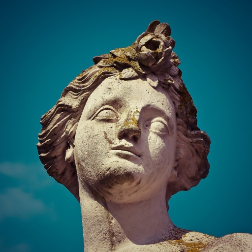
Loading an image with javax.imageio is easy:
private void createTextureImage() {
BufferedImage image;
try (var stream = Application.class.getResourceAsStream("/texture/texture.png")) {
if (stream == null) {
throw new RuntimeException("Failed to load texture image");
}
image = ImageIO.read(stream);
}
catch (IOException e) {
throw new RuntimeException("Failed to load texture image", e);
}
var width = image.getWidth();
var height = image.getHeight();
var imageSize = width * height;
var imageSizeBytes = imageSize * 4;
}
Staging buffer
We're now going to create a buffer in host visible memory so that we can use vkMapMemory and copy the pixels to it. The buffer should be in host visible memory so that we can map it, and it should be usable as a transfer source so that we can copy it to an image later on:
try (var arena = Arena.ofConfined()) {
var pair = createBuffer(
imageSizeBytes,
VkBufferUsageFlags.VK_BUFFER_USAGE_TRANSFER_SRC_BIT,
VkMemoryPropertyFlags.VK_MEMORY_PROPERTY_HOST_VISIBLE_BIT
| VkMemoryPropertyFlags.VK_MEMORY_PROPERTY_HOST_COHERENT_BIT
);
var stagingBuffer = pair.first;
var stagingBufferMemory = pair.second;
}
We can then directly copy the pixel values that we got from the image loading library to the buffer:
var ppData = PointerBuffer.allocate(arena);
var result = deviceCommands.vkMapMemory(device, stagingBufferMemory, 0, imageSizeBytes, 0, ppData.segment());
if (result != VkResult.VK_SUCCESS) {
throw new RuntimeException("Failed to map texture image memory, vulkan error code: " + VkResult.explain(result));
}
var buffer = new ByteBuffer(ppData.read().reinterpret(imageSizeBytes));
for (int y = 0; y < height; y++) {
for (int x = 0; x < width; x++) {
var color = new Color(image.getRGB(x, y), true);
var linearIndex = y * width + x;
buffer.write(linearIndex * 4L, (byte) color.getRed());
buffer.write(linearIndex * 4L + 1, (byte) color.getGreen());
buffer.write(linearIndex * 4L + 2, (byte) color.getBlue());
buffer.write(linearIndex * 4L + 3, (byte) color.getAlpha());
}
}
deviceCommands.vkUnmapMemory(device, stagingBufferMemory);
Writing pixel by pixel might not be the optimal way of doing this, but it's simple and works for now. You may use a more efficient image loading and pixel copying method in real-world application if you want.
Texture Image
Although we could set up the shader to access the pixel values in the buffer, it's better to use image objects in Vulkan for this purpose. Image objects will make it easier and faster to retrieve colors by allowing us to use 2D coordinates, for one. Pixels within an image object are known as texels and we'll use that name from this point on. Add the following new class members:
private VkImage textureImage;
private VkDeviceMemory textureImageMemory;
The parameters for an image are specified in a VkImageCreateInfo struct:
var imageInfo = VkImageCreateInfo.allocate(arena);
imageInfo.imageType(VkImageType.VK_IMAGE_TYPE_2D);
imageInfo.extent().width(width);
imageInfo.extent().height(height);
imageInfo.extent().depth(1);
imageInfo.mipLevels(1);
imageInfo.arrayLayers(1);
The image type, specified in the imageType field, tells Vulkan with what kind of coordinate system the texels in the image are going to be addressed. It is possible to create 1D, 2D and 3D images. One dimensional images can be used to store an array of data or gradient, two-dimensional images are mainly used for textures, and three-dimensional images can be used to store voxel volumes, for example. The extent field specifies the dimensions of the image, basically how many texels there are on each axis. That's why depth must be 1 instead of 0. Our texture will not be an array, and we won't be using mipmapping for now.
imageInfo.format(VkFormat.VK_FORMAT_R8G8B8A8_SRGB);
Vulkan supports many possible image formats, but we should use the same format for the texels as the pixels in the buffer, otherwise the copy operation will fail.
imageInfo.tiling(VkImageTiling.VK_IMAGE_TILING_OPTIMAL);
The tiling field can have one of two values:
VK_IMAGE_TILING_LINEAR: Texels are laid out in row-major order like our pixels arrayVK_IMAGE_TILING_OPTIMAL: Texels are laid out in an implementation defined order for optimal access
Unlike the layout of an image, the tiling mode cannot be changed at a later time. If you want to be able to directly access texels in the memory of the image, then you must use VK_IMAGE_TILING_LINEAR. We will be using a staging buffer instead of a staging image, so this won't be necessary. We will be using VK_IMAGE_TILING_OPTIMAL for efficient access from the shader.
imageInfo.initialLayout(VkImageLayout.VK_IMAGE_LAYOUT_UNDEFINED);
There are only two possible values for the initialLayout of an image:
VK_IMAGE_LAYOUT_UNDEFINED: Not usable by the GPU and the very first transition will discard the texels.VK_IMAGE_LAYOUT_PREINITIALIZED: Not usable by the GPU, but the first transition will preserve the texels.
There are few situations where it is necessary for the texels to be preserved during the first transition. One example, however, would be if you wanted to use an image as a staging image in combination with the VK_IMAGE_TILING_LINEAR layout. In that case, you'd want to upload the texel data to it and then transition the image to be a transfer source without losing the data. In our case, however, we're first going to transition the image to be a transfer destination and then copy texel data to it from a buffer object, so we don't need this property and can safely use VK_IMAGE_LAYOUT_UNDEFINED.
imageInfo.usage(VkImageUsageFlags.VK_IMAGE_USAGE_TRANSFER_DST_BIT | VkImageUsageFlags.VK_IMAGE_USAGE_SAMPLED_BIT);
The usage field has the same semantics as the one during buffer creation. The image is going to be used as destination for the buffer copy, so it should be set up as a transfer destination. We also want to be able to access the image from the shader to color our mesh, so the usage should include VK_IMAGE_USAGE_SAMPLED_BIT.
imageInfo.sharingMode(VkSharingMode.VK_SHARING_MODE_EXCLUSIVE);
The image will only be used by one queue family: the one that supports graphics (and therefore also) transfer operations.
imageInfo.samples(VkSampleCountFlags.VK_SAMPLE_COUNT_1_BIT);
imageInfo.flags(0); // Optional
The samples flag is related to multisampling. This is only relevant for images that will be used as attachments, so stick to one sample. There are some optional flags for images that are related to sparse images. Sparse images are images where only certain regions are actually backed by memory. If you were using a 3D texture for a voxel terrain, for example, then you could use this to avoid allocating memory to store large volumes of "air" values. We won't be using it in this tutorial, so leave it to its default value of 0.
var pTextureImage = VkImage.Buffer.allocate(arena);
result = deviceCommands.vkCreateImage(device, imageInfo, null, pTextureImage);
if (result != VkResult.VK_SUCCESS) {
throw new RuntimeException("Failed to create image, vulkan error code: " + VkResult.explain(result));
}
textureImage = pTextureImage.read();
The image is created using vkCreateImage, which doesn't have any particularly noteworthy parameters. It is possible that the VK_FORMAT_R8G8B8A8_SRGB format is not supported by the graphics hardware. You should have a list of acceptable alternatives and go with the best one that is supported. However, support for this particular format is so widespread that we'll skip this step. Using different formats would also require annoying conversions. We will get back to this in the depth buffer chapter, where we'll implement such a system.
var memoryRequirements = VkMemoryRequirements.allocate(arena);
deviceCommands.vkGetImageMemoryRequirements(device, textureImage, memoryRequirements);
var allocInfo = VkMemoryAllocateInfo.allocate(arena);
allocInfo.allocationSize(memoryRequirements.size());
allocInfo.memoryTypeIndex(findMemoryType(
memoryRequirements.memoryTypeBits(),
VkMemoryPropertyFlags.VK_MEMORY_PROPERTY_DEVICE_LOCAL_BIT
));
var pTextureImageMemory = VkDeviceMemory.Buffer.allocate(arena);
result = deviceCommands.vkAllocateMemory(device, allocInfo, null, pTextureImageMemory);
if (result != VkResult.VK_SUCCESS) {
throw new RuntimeException("Failed to allocate image memory, vulkan error code: " + VkResult.explain(result));
}
textureImageMemory = pTextureImageMemory.read();
deviceCommands.vkBindImageMemory(device, textureImage, textureImageMemory, 0);
Allocating memory for an image works in exactly the same way as allocating memory for a buffer. Use vkGetImageMemoryRequirements instead of vkGetBufferMemoryRequirements, and use vkBindImageMemory instead of vkBindBufferMemory.
This function is already getting quite large and there'll be a need to create more images in later chapters, so we should abstract image creation into a createImage function, like we did for buffers. Create the function and move the image object creation and memory allocation to it:
private Pair<VkImage, VkDeviceMemory> createImage(
int width,
int height,
@enumtype(VkFormat.class) int format,
@enumtype(VkImageTiling.class) int tiling,
@enumtype(VkImageUsageFlags.class) int usage,
@enumtype(VkMemoryPropertyFlags.class) int properties
) {
try (var arena = Arena.ofConfined()) {
var imageInfo = VkImageCreateInfo.allocate(arena);
imageInfo.imageType(VkImageType.VK_IMAGE_TYPE_2D);
imageInfo.extent().width(width);
imageInfo.extent().height(height);
imageInfo.extent().depth(1);
imageInfo.mipLevels(1);
imageInfo.arrayLayers(1);
imageInfo.format(format);
imageInfo.tiling(tiling);
imageInfo.initialLayout(VkImageLayout.VK_IMAGE_LAYOUT_UNDEFINED);
imageInfo.usage(usage);
imageInfo.samples(VkSampleCountFlags.VK_SAMPLE_COUNT_1_BIT);
imageInfo.sharingMode(VkSharingMode.VK_SHARING_MODE_EXCLUSIVE);
var pImage = VkImage.Buffer.allocate(arena);
var result = deviceCommands.vkCreateImage(device, imageInfo, null, pImage);
if (result != VkResult.VK_SUCCESS) {
throw new RuntimeException("Failed to create image, vulkan error code: " + VkResult.explain(result));
}
var image = pImage.read();
var memRequirements = VkMemoryRequirements.allocate(arena);
deviceCommands.vkGetImageMemoryRequirements(device, image, memRequirements);
var allocInfo = VkMemoryAllocateInfo.allocate(arena);
allocInfo.allocationSize(memRequirements.size());
allocInfo.memoryTypeIndex(findMemoryType(memRequirements.memoryTypeBits(), properties));
var pMemory = VkDeviceMemory.Buffer.allocate(arena);
result = deviceCommands.vkAllocateMemory(device, allocInfo, null, pMemory);
if (result != VkResult.VK_SUCCESS) {
throw new RuntimeException("Failed to allocate image memory, vulkan error code: " + VkResult.explain(result));
}
var memory = pMemory.read();
deviceCommands.vkBindImageMemory(device, image, memory, 0);
return new Pair<>(image, memory);
}
}
I've made the width, height, format, tiling mode, usage, and memory properties parameters, because these will all vary between the images we'll be creating throughout this tutorial.
The createTextureImage function can now be simplified to:
private void createTextureImage() {
BufferedImage image;
try (var stream = Application.class.getResourceAsStream("/texture/texture.jpg")) {
if (stream == null) {
throw new RuntimeException("Failed to load texture image");
}
image = ImageIO.read(stream);
}
catch (IOException e) {
throw new RuntimeException("Failed to load texture image", e);
}
var width = image.getWidth();
var height = image.getHeight();
var imageSize = width * height;
var imageSizeBytes = imageSize * 4;
try (var arena = Arena.ofConfined()) {
var pair = createBuffer(
imageSizeBytes,
VkBufferUsageFlags.VK_BUFFER_USAGE_TRANSFER_SRC_BIT,
VkMemoryPropertyFlags.VK_MEMORY_PROPERTY_HOST_VISIBLE_BIT
| VkMemoryPropertyFlags.VK_MEMORY_PROPERTY_HOST_COHERENT_BIT
);
var stagingBuffer = pair.first;
var stagingBufferMemory = pair.second;
var ppData = PointerBuffer.allocate(arena);
var result = deviceCommands.vkMapMemory(device, stagingBufferMemory, 0, imageSizeBytes, 0, ppData.segment());
if (result != VkResult.VK_SUCCESS) {
throw new RuntimeException("Failed to map texture image memory, vulkan error code: " + VkResult.explain(result));
}
var buffer = new ByteBuffer(ppData.read().reinterpret(imageSizeBytes));
for (int y = 0; y < height; y++) {
for (int x = 0; x < width; x++) {
var color = new Color(image.getRGB(x, y), true);
var linearIndex = y * width + x;
buffer.write(linearIndex * 4L, (byte) color.getRed());
buffer.write(linearIndex * 4L + 1, (byte) color.getGreen());
buffer.write(linearIndex * 4L + 2, (byte) color.getBlue());
buffer.write(linearIndex * 4L + 3, (byte) color.getAlpha());
}
}
deviceCommands.vkUnmapMemory(device, stagingBufferMemory);
var pair2 = createImage(
width,
height,
VkFormat.VK_FORMAT_R8G8B8A8_SRGB,
VkImageTiling.VK_IMAGE_TILING_OPTIMAL,
VkImageUsageFlags.VK_IMAGE_USAGE_TRANSFER_DST_BIT
| VkImageUsageFlags.VK_IMAGE_USAGE_SAMPLED_BIT,
VkMemoryPropertyFlags.VK_MEMORY_PROPERTY_DEVICE_LOCAL_BIT
);
textureImage = pair2.first;
textureImageMemory = pair2.second;
}
}
Layout transitions
The function we're going to write now involves recording and executing a command buffer again, so now's a good time to move that logic into a helper function or two:
private VkCommandBuffer beginSingleTimeCommands() {
try (var arena = Arena.ofConfined()) {
var allocInfo = VkCommandBufferAllocateInfo.allocate(arena);
allocInfo.level(VkCommandBufferLevel.VK_COMMAND_BUFFER_LEVEL_PRIMARY);
allocInfo.commandPool(commandPool);
allocInfo.commandBufferCount(1);
var pCommandBuffer = VkCommandBuffer.Buffer.allocate(arena);
var result = deviceCommands.vkAllocateCommandBuffers(device, allocInfo, pCommandBuffer);
if (result != VkResult.VK_SUCCESS) {
throw new RuntimeException("Failed to allocate command buffer, vulkan error code: " + VkResult.explain(result));
}
var commandBuffer = pCommandBuffer.read();
var beginInfo = VkCommandBufferBeginInfo.allocate(arena);
beginInfo.flags(VkCommandBufferUsageFlags.VK_COMMAND_BUFFER_USAGE_ONE_TIME_SUBMIT_BIT);
result = deviceCommands.vkBeginCommandBuffer(commandBuffer, beginInfo);
if (result != VkResult.VK_SUCCESS) {
throw new RuntimeException("Failed to begin recording command buffer, vulkan error code: " + VkResult.explain(result));
}
return commandBuffer;
}
}
private void endSingleTimeCommands(VkCommandBuffer commandBuffer) {
deviceCommands.vkEndCommandBuffer(commandBuffer);
try (var arena = Arena.ofConfined()) {
var submitInfo = VkSubmitInfo.allocate(arena);
submitInfo.commandBufferCount(1);
var pCommandBuffers = VkCommandBuffer.Buffer.allocate(arena);
pCommandBuffers.write(commandBuffer);
submitInfo.pCommandBuffers(pCommandBuffers);
deviceCommands.vkQueueSubmit(graphicsQueue, 1, submitInfo, null);
deviceCommands.vkQueueWaitIdle(graphicsQueue);
deviceCommands.vkFreeCommandBuffers(device, commandPool, 1, pCommandBuffers);
}
}
The code for these functions is based on the existing code in copyBuffer. You can now simplify that function to:
private void copyBuffer(VkBuffer srcBuffer, VkBuffer dstBuffer, int size) {
try (var arena = Arena.ofConfined()) {
var commandBuffer = beginSingleTimeCommands();
var copyRegion = VkBufferCopy.allocate(arena);
copyRegion.size(size);
deviceCommands.vkCmdCopyBuffer(commandBuffer, srcBuffer, dstBuffer, 1, copyRegion);
endSingleTimeCommands(commandBuffer);
}
}
If we were still using buffers, then we could now write a function to record and execute vkCmdCopyBufferToImage to finish the job, but this command requires the image to be in the right layout first. Create a new function to handle layout transitions:
private void transitionImageLayout(
VkImage image,
@enumtype(VkFormat.class) int format,
@enumtype(VkImageLayout.class) int oldLayout,
@enumtype(VkImageLayout.class) int newLayout
) {
try (var arena = Arena.ofConfined()) {
var commandBuffer = beginSingleTimeCommands();
endSingleTimeCommands(commandBuffer);
}
}
One of the most common ways to perform layout transitions is using an image memory barrier. A pipeline barrier like that is generally used to synchronize access to resources, like ensuring that a write to a buffer completes before reading from it, but it can also be used to transition image layouts and transfer queue family ownership when VK_SHARING_MODE_EXCLUSIVE is used. There is an equivalent buffer memory barrier to do this for buffers.
var barrier = VkImageMemoryBarrier.allocate(arena);
barrier.oldLayout(oldLayout);
barrier.newLayout(newLayout);
The first two fields specify layout transition. It is possible to use VK_IMAGE_LAYOUT_UNDEFINED as oldLayout if you don't care about the existing contents of the image.
barrier.srcQueueFamilyIndex(Constants.VK_QUEUE_FAMILY_IGNORED);
barrier.dstQueueFamilyIndex(Constants.VK_QUEUE_FAMILY_IGNORED);
If you are using the barrier to transfer queue family ownership, then these two fields should be the indices of the queue families. They must be set to VK_QUEUE_FAMILY_IGNORED if you don't want to do this (not the default value!).
barrier.image(image);
var subResourceRange = barrier.subresourceRange();
subResourceRange.aspectMask(VkImageAspectFlags.VK_IMAGE_ASPECT_COLOR_BIT);
subResourceRange.baseMipLevel(0);
subResourceRange.levelCount(1);
subResourceRange.baseArrayLayer(0);
subResourceRange.layerCount(1);
The image and subresourceRange specify the image that is affected and the specific part of the image. Our image is not an array and does not have mipmapping levels, so only one level and layer are specified.
barrier.srcAccessMask(0); // TODO
barrier.dstAccessMask(0); // TODO
Barriers are primarily used for synchronization purposes, so you must specify which types of operations that involve the resource must happen before the barrier, and which operations that involve the resource must wait on the barrier. We need to do that despite already using vkQueueWaitIdle to manually synchronize. The right values depend on the old and new layout, so we'll get back to this once we've figured out which transitions we're going to use.
deviceCommands.vkCmdPipelineBarrier(
commandBuffer,
0, // TODO
0, // TODO
0,
0, null,
0, null,
1, barrier
);
All types of pipeline barriers are submitted using the same function. The first parameter after the command buffer specifies in which pipeline stage the operations occur that should happen before the barrier. The second parameter specifies the pipeline stage in which operations will wait on the barrier. The pipeline stages that you are allowed to specify before and after the barrier depend on how you use the resource before and after the barrier. The allowed values are listed in this table of the specification. For example, if you're going to read from a uniform after the barrier, you would specify a usage of VK_ACCESS_UNIFORM_READ_BIT and the earliest shader that will read from the uniform as pipeline stage, for example VK_PIPELINE_STAGE_FRAGMENT_SHADER_BIT. It would not make sense to specify a non-shader pipeline stage for this type of usage and the validation layers will warn you when you specify a pipeline stage that does not match the type of usage.
The third parameter is either 0 or VK_DEPENDENCY_BY_REGION_BIT. The latter turns the barrier into a per-region condition. That means that the implementation is allowed to already begin reading from the parts of a resource that were written so far, for example.
The last three pairs of parameters reference arrays of pipeline barriers of the three available types: memory barriers, buffer memory barriers, and image memory barriers like the one we're using here. Note that we're not using the VkFormat parameter yet, but we'll be using that one for special transitions in the depth buffer chapter.
Copying buffer to image
Before we get back to createTextureImage, we're going to write one more helper function: copyBufferToImage:
private void copyBufferToImage(
VkBuffer buffer,
VkImage image,
int width,
int height
) {
try (var arena = Arena.ofConfined()) {
var commandBuffer = beginSingleTimeCommands();
endSingleTimeCommands(commandBuffer);
}
}
Just like with buffer copies, you need to specify which part of the buffer is going to be copied to which part of the image. This happens through VkBufferImageCopy structs:
var region = VkBufferImageCopy.allocate(arena);
region.bufferOffset(0);
region.bufferRowLength(0);
region.bufferImageHeight(0);
var imageSubresource = region.imageSubresource();
imageSubresource.aspectMask(VkImageAspectFlags.VK_IMAGE_ASPECT_COLOR_BIT);
imageSubresource.mipLevel(0);
imageSubresource.baseArrayLayer(0);
imageSubresource.layerCount(1);
var imageOffset = region.imageOffset();
imageOffset.x(0);
imageOffset.y(0);
imageOffset.z(0);
var imageExtent = region.imageExtent();
imageExtent.width(width);
imageExtent.height(height);
imageExtent.depth(1);
Most of these fields are self-explanatory. The bufferOffset specifies the byte offset in the buffer at which the pixel values start. The bufferRowLength and bufferImageHeight fields specify how the pixels are laid out in memory. For example, you could have some padding bytes between rows of the image. Specifying 0 for both indicates that the pixels are simply tightly packed like they are in our case. The imageSubresource, imageOffset and imageExtent fields indicate to which part of the image we want to copy the pixels.
Buffer to image copy operations are enqueued using the vkCmdCopyBufferToImage function:
deviceCommands.vkCmdCopyBufferToImage(
commandBuffer,
buffer,
image,
VkImageLayout.VK_IMAGE_LAYOUT_TRANSFER_DST_OPTIMAL,
1,
region
);
The fourth parameter indicates which layout the image is currently using. I'm assuming here that the image has already been transitioned to the layout that is optimal for copying pixels to. Right now we're only copying one chunk of pixels to the whole image, but it's possible to specify an array of VkBufferImageCopy to perform many different copies from this buffer to the image in one operation.
Preparing the texture image
We now have all the tools we need to finish setting up the texture image, so we're going back to the createTextureImage function. The last thing we did there was creating the texture image. The next step is to copy the staging buffer to the texture image. This involves two steps:
- Transition the texture image to
VK_IMAGE_LAYOUT_TRANSFER_DST_OPTIMAL - Execute the buffer to image copy operation
This is easy to do with the functions we just created:
transitionImageLayout(
textureImage,
VkFormat.VK_FORMAT_R8G8B8A8_SRGB,
VkImageLayout.VK_IMAGE_LAYOUT_UNDEFINED,
VkImageLayout.VK_IMAGE_LAYOUT_TRANSFER_DST_OPTIMAL
);
copyBufferToImage(stagingBuffer, textureImage, width, height);
The image was created with the VK_IMAGE_LAYOUT_UNDEFINED layout, so that one should be specified as old layout when transitioning textureImage. Remember that we can do this because we don't care about its contents before performing the copy operation.
To be able to start sampling from the texture image in the shader, we need one last transition to prepare it for shader access:
transitionImageLayout(
textureImage,
VkFormat.VK_FORMAT_R8G8B8A8_SRGB,
VkImageLayout.VK_IMAGE_LAYOUT_TRANSFER_DST_OPTIMAL,
VkImageLayout.VK_IMAGE_LAYOUT_SHADER_READ_ONLY_OPTIMAL
);
Transition barrier masks
If you run your application with validation layers enabled now, then you'll see that it complains about the access masks and pipeline stages in transitionImageLayout being invalid. We still need to set those based on the layouts in the transition.
There are two transitions we need to handle:
- Undefined → transfer destination: transfer writes that don't need to wait on anything
- Transfer destination → shader reading: shader reads should wait on transfer writes, specifically the shader reads in the fragment shader, because that's where we're going to use the texture
These rules are specified using the following access masks and pipeline stages:
@enumtype(VkPipelineStageFlags.class) int sourceStage;
@enumtype(VkPipelineStageFlags.class) int destinationStage;
if (oldLayout == VkImageLayout.VK_IMAGE_LAYOUT_UNDEFINED
&& newLayout == VkImageLayout.VK_IMAGE_LAYOUT_TRANSFER_DST_OPTIMAL) {
barrier.srcAccessMask(0);
barrier.dstAccessMask(VkAccessFlags.VK_ACCESS_TRANSFER_WRITE_BIT);
sourceStage = VkPipelineStageFlags.VK_PIPELINE_STAGE_TOP_OF_PIPE_BIT;
destinationStage = VkPipelineStageFlags.VK_PIPELINE_STAGE_TRANSFER_BIT;
}
else if (oldLayout == VkImageLayout.VK_IMAGE_LAYOUT_TRANSFER_DST_OPTIMAL
&& newLayout == VkImageLayout.VK_IMAGE_LAYOUT_SHADER_READ_ONLY_OPTIMAL) {
barrier.srcAccessMask(VkAccessFlags.VK_ACCESS_TRANSFER_WRITE_BIT);
barrier.dstAccessMask(VkAccessFlags.VK_ACCESS_SHADER_READ_BIT);
sourceStage = VkPipelineStageFlags.VK_PIPELINE_STAGE_TRANSFER_BIT;
destinationStage = VkPipelineStageFlags.VK_PIPELINE_STAGE_FRAGMENT_SHADER_BIT;
}
else {
throw new RuntimeException(
"Unsupported layout transition from "
+ VkImageLayout.explain(oldLayout)
+ " to "
+ VkImageLayout.explain(newLayout)
);
}
deviceCommands.vkCmdPipelineBarrier(
commandBuffer,
sourceStage,
destinationStage,
0,
0, null,
0, null,
1, barrier
);
As you can see in the aforementioned table, transfer writes must occur in the pipeline transfer stage. Since the writes don't have to wait on anything, you may specify an empty access mask and the earliest possible pipeline stage VK_PIPELINE_STAGE_TOP_OF_PIPE_BIT for the pre-barrier operations. It should be noted that VK_PIPELINE_STAGE_TRANSFER_BIT is not a real stage within the graphics and compute pipelines. It is more of a pseudo-stage where transfers happen. See the documentation for more information and other examples of pseudo-stages.
The image will be written in the same pipeline stage and subsequently read by the fragment shader, which is why we specify shader reading access in the fragment shader pipeline stage.
If we need to do more transitions in the future, then we'll extend the function. The application should now run successfully, although there are of course no visual changes yet.
One thing to note is that command buffer submission results in implicit VK_ACCESS_HOST_WRITE_BIT synchronization at the beginning. Since the transitionImageLayout function executes a command buffer with only a single command, you could use this implicit synchronization and set srcAccessMask to 0 if you ever needed a VK_ACCESS_HOST_WRITE_BIT dependency in a layout transition. It's up to you if you want to be explicit about it or not, but I'm personally not a fan of relying on these OpenGL-like "hidden" operations.
There is actually a special type of image layout that supports all operations, VK_IMAGE_LAYOUT_GENERAL. The problem with it, of course, is that it doesn't necessarily offer the best performance for any operation. It is required for some special cases, like using an image as both input and output, or for reading an image after it has left the pre-initialized layout.
All the helper functions that submit commands so far have been set up to execute synchronously by waiting for the queue to become idle. For practical applications it is recommended to combine these operations in a single command buffer and execute them asynchronously for higher throughput, especially the transitions and copy in the createTextureImage function. Try to experiment with this by creating a setupCommandBuffer that the helper functions record commands into, and add a flushSetupCommands to execute the commands that have been recorded so far. It's best to do this after the texture mapping works to check if the texture resources are still set up correctly.
Cleanup
Finish the createTextureImage function by cleaning up the staging buffer and its memory at the end:
deviceCommands.vkDestroyBuffer(device, stagingBuffer, null);
deviceCommands.vkFreeMemory(device, stagingBufferMemory, null);
The main texture image is used until the end of the program:
private void cleanup() {
// ...
cleanupSwapChain();
deviceCommands.vkDestroyImageView(device, textureImageView, null);
deviceCommands.vkDestroyImage(device, textureImage, null);
}
The image now contains the texture, but we still need a way to access it from the graphics pipeline. We'll work on that in the next chapter.
Image view and sampler
In this chapter we're going to create two more resources that are needed for the graphics pipeline to sample an image. The first resource is one that we've already seen before while working with the swap chain images, but the second one is new - it relates to how the shader will read texels from the image.
Texture image view
We've seen before, with the swap chain images and the framebuffer, that images are accessed through image views rather than directly. We will also need to create such an image view for the texture image.
Add a class member to hold a VkImageView for the texture image and create a new function createTextureImageView where we'll create it:
private VkImageView textureImageView;
// ...
private void initVulkan() {
// ...
createTextureImage();
createTextureImageView();
// ...
}
private void createTextureImageView() {
}
The code for this function can be based directly on createImageViews. The only two changes you have to make are the format and the image:
var viewInfo = VkImageViewCreateInfo.allocate(arena);
viewInfo.image(textureImage);
viewInfo.viewType(VkImageViewType.VK_IMAGE_VIEW_TYPE_2D);
viewInfo.format(VkFormat.VK_FORMAT_R8G8B8A8_SRGB);
var subresourceRange = viewInfo.subresourceRange();
subresourceRange.aspectMask(VkImageAspectFlags.VK_IMAGE_ASPECT_COLOR_BIT);
subresourceRange.baseMipLevel(0);
subresourceRange.levelCount(1);
subresourceRange.baseArrayLayer(0);
subresourceRange.layerCount(1);
I've left out the explicit viewInfo.components initialization, because VK_COMPONENT_SWIZZLE_IDENTITY is defined as 0 anyway. Finish creating the image view by calling vkCreateImageView:
var pImageView = VkImageView.Buffer.allocate(arena);
var result = deviceCommands.vkCreateImageView(device, viewInfo, null, pImageView);
if (result != VkResult.VK_SUCCESS) {
throw new RuntimeException("Failed to create texture image view, vulkan error code: " + VkResult.explain(result));
}
textureImageView = pImageView.read();
Because so much of the logic is duplicated from createImageViews, you may wish to abstract it into a new createImageView function:
private VkImageView createImageView(VkImage image, @enumtype(VkFormat.class) int format) {
try (var arena = Arena.ofConfined()) {
var viewInfo = VkImageViewCreateInfo.allocate(arena);
viewInfo.image(image);
viewInfo.viewType(VkImageViewType.VK_IMAGE_VIEW_TYPE_2D);
viewInfo.format(format);
var subresourceRange = viewInfo.subresourceRange();
subresourceRange.aspectMask(VkImageAspectFlags.VK_IMAGE_ASPECT_COLOR_BIT);
subresourceRange.baseMipLevel(0);
subresourceRange.levelCount(1);
subresourceRange.baseArrayLayer(0);
subresourceRange.layerCount(1);
var pImageView = VkImageView.Buffer.allocate(arena);
var result = deviceCommands.vkCreateImageView(device, viewInfo, null, pImageView);
if (result != VkResult.VK_SUCCESS) {
throw new RuntimeException("Failed to create image view, vulkan error code: " + VkResult.explain(result));
}
return pImageView.read();
}
}
The createTextureImageView function can now be simplified to:
private void createTextureImageView() {
textureImageView = createImageView(textureImage, VkFormat.VK_FORMAT_R8G8B8A8_SRGB);
}
And createImageViews can be simplified to:
private void createImageViews() {
swapChainImageViews = new VkImageView[swapChainImages.length];
for (int i = 0; i < swapChainImages.length; i++) {
swapChainImageViews[i] = createImageView(swapChainImages[i], swapChainImageFormat);
}
}
Make sure to destroy the image view at the end of the program, right before destroying the image itself:
private void cleanup() {
// ...
deviceCommands.vkDestroyImageView(device, textureImageView, null);
deviceCommands.vkDestroyImage(device, textureImage, null);
// ...
}
Samplers
It is possible for shaders to read texels directly from images, but that is not very common when they are used as textures. Textures are usually accessed through samplers, which will apply filtering and transformations to compute the final color that is retrieved.
These filters are helpful to deal with problems like oversampling. Consider a texture that is mapped to geometry with more fragments than texels. If you simply took the closest texel for the texture coordinate in each fragment, then you would get a result like the first image:
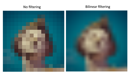
If you combined the 4 closest texels through linear interpolation, then you would get a smoother result like the one on the right. Of course your application may have art style requirements that fit the left style more (think Minecraft), but the right is preferred in conventional graphics applications. A sampler object automatically applies this filtering for you when reading a color from the texture.
Under sampling is the opposite problem, where you have more texels than fragments. This will lead to artifacts when sampling high frequency patterns like a checkerboard texture at a sharp angle:
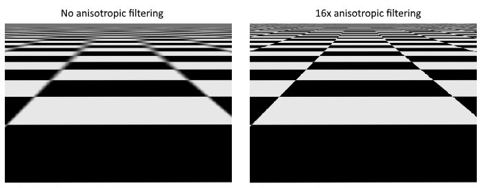
As shown in the left image, the texture turns into a blurry mess in the distance. The solution to this is anisotropic filtering, which can also be applied automatically by a sampler.
Aside from these filters, a sampler can also take care of transformations. It determines what happens when you try to read texels outside the image through its addressing mode. The image below displays some of the possibilities:
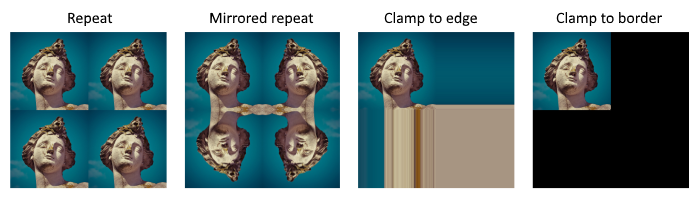
We will now create a function createTextureSampler to set up such a sampler object. We'll be using that sampler to read colors from the texture in the shader later on.
private void initVulkan() {
// ...
createTextureImage();
createTextureImageView();
createTextureSampler();
// ...
}
// ...
private void createTextureSampler() {
}
Samplers are configured through a VkSamplerCreateInfo structure, which specifies all filters and transformations that it should apply.
try (var arena = Arena.ofConfined()) {
var samplerInfo = VkSamplerCreateInfo.allocate(arena);
samplerInfo.magFilter(VkFilter.VK_FILTER_LINEAR);
samplerInfo.minFilter(VkFilter.VK_FILTER_LINEAR);
}
The magFilter and minFilter fields specify how to interpolate texels that are magnified or minified. Magnification concerns the oversampling problem describes above, and minification concerns undersampling. The choices are VK_FILTER_NEAREST and VK_FILTER_LINEAR, corresponding to the modes demonstrated in the images above.
samplerInfo.addressModeU(VkSamplerAddressMode.VK_SAMPLER_ADDRESS_MODE_REPEAT);
samplerInfo.addressModeV(VkSamplerAddressMode.VK_SAMPLER_ADDRESS_MODE_REPEAT);
samplerInfo.addressModeW(VkSamplerAddressMode.VK_SAMPLER_ADDRESS_MODE_REPEAT);
The addressing mode can be specified per axis using the addressMode fields. The available values are listed below. Most of these are demonstrated in the image above. Note that the axes are called U, V and W instead of X, Y and Z. This is a convention for texture space coordinates.
VK_SAMPLER_ADDRESS_MODE_REPEAT: Repeat the texture when going beyond the image dimensions.VK_SAMPLER_ADDRESS_MODE_MIRRORED_REPEAT: Like repeat, but inverts the coordinates to mirror the image when going beyond the dimensions.VK_SAMPLER_ADDRESS_MODE_CLAMP_TO_EDGE: Take the color of the edge closest to the coordinate beyond the image dimensions.VK_SAMPLER_ADDRESS_MODE_MIRROR_CLAMP_TO_EDGE: Like clamp to edge, but instead uses the edge opposite to the closest edge.VK_SAMPLER_ADDRESS_MODE_CLAMP_TO_BORDER: Return a solid color when sampling beyond the dimensions of the image.
It doesn't really matter which addressing mode we use here, because we're not going to sample outside of the image in this tutorial. However, the repeat mode is probably the most common mode, because it can be used to tile textures like floors and walls.
samplerInfo.anisotropyEnable(Constants.VK_TRUE);
samplerInfo.maxAnisotropy(/* ???*/);
These two fields specify if anisotropic filtering should be used. There is no reason not to use this unless performance is a concern. The maxAnisotropy field limits the amount of texel samples that can be used to calculate the final color. A lower value results in better performance, but lower quality results. To figure out which value we can use, we need to retrieve the properties of the physical device like so:
var properties = VkPhysicalDeviceProperties.allocate(arena);
instanceCommands.vkGetPhysicalDeviceProperties(physicalDevice, properties);
If you look at the documentation for the VkPhysicalDeviceProperties structure, you'll see that it contains a VkPhysicalDeviceLimits member named limits. This struct in turn has a member called maxSamplerAnisotropy and this is the maximum value we can specify for maxAnisotropy. If we want to go for maximum quality, we can simply use that value directly:
samplerInfo.maxAnisotropy(properties.limits().maxSamplerAnisotropy());
You can either query the properties at the beginning of your program and pass them around to the functions that need them, or query them in the createTextureSampler function itself.
samplerInfo.borderColor(VkBorderColor.VK_BORDER_COLOR_INT_OPAQUE_BLACK);
The borderColor field specifies which color is returned when sampling beyond the image with clamp to border addressing mode. It is possible to return black, white or transparent in either float or int formats. You cannot specify an arbitrary color.
samplerInfo.unnormalizedCoordinates(Constants.VK_FALSE);
The unnormalizedCoordinates field specifies which coordinate system you want to use to address texels in an image. If this field is VK_TRUE, then you can simply use coordinates within the [0, texWidth) and [0, texHeight) range. If it is VK_FALSE, then the texels are addressed using the [0, 1) range on all axes. Real-world applications almost always use normalized coordinates, because then it's possible to use textures of varying resolutions with the exact same coordinates.
samplerInfo.compareEnable(Constants.VK_FALSE);
samplerInfo.compareOp(VkCompareOp.VK_COMPARE_OP_ALWAYS);
If a comparison function is enabled, then texels will first be compared to a value, and the result of that comparison is used in filtering operations. This is mainly used for percentage-closer filtering on shadow maps. We'll look at this in a future chapter.
samplerInfo.mipmapMode(VkSamplerMipmapMode.VK_SAMPLER_MIPMAP_MODE_LINEAR);
samplerInfo.mipLodBias(0.0f);
samplerInfo.minLod(0.0f);
samplerInfo.maxLod(0.0f);
All of these fields apply to mipmapping. We will look at mipmapping in a later chapter, but basically it's another type of filter that can be applied.
The functioning of the sampler is now fully defined. Add a class member to hold the handle of the sampler object and create the sampler with vkCreateSampler:
private VkSampler textureSampler;
// ...
var pSampler = VkSampler.Buffer.allocate(arena);
var result = deviceCommands.vkCreateSampler(device, samplerInfo, null, pSampler);
if (result != VkResult.VK_SUCCESS) {
throw new RuntimeException("Failed to create texture sampler, vulkan error code: " + VkResult.explain(result));
}
textureSampler = pSampler.read();
Note the sampler does not reference a VkImage anywhere. The sampler is a distinct object that provides an interface to extract colors from a texture. It can be applied to any image you want, whether it is 1D, 2D or 3D. This is different from many older APIs, which combined texture images and filtering into a single state.
Destroy the sampler at the end of the program when we'll no longer be accessing the image:
private void cleanup() {
// ...
deviceCommands.vkDestroySampler(device, textureSampler, null);
deviceCommands.vkDestroyImageView(device, textureImageView, null);
// ...
}
Anisotropy device feature
If you run your program right now, you'll see a validation layer message like this:
Validation layer: Validation Error: [ VUID-VkSamplerCreateInfo-anisotropyEnable-01070 ] Object 0: handle = 0x1f8c82e62e0, type = VK_OBJECT_TYPE_DEVICE; | MessageID = 0x56f192bc | vkCreateSampler(): Anisotropic sampling feature is not enabled, pCreateInfo->anisotropyEnable must be VK_FALSE. The Vulkan spec states: If the samplerAnisotropy feature is not enabled, anisotropyEnable must be VK_FALSE (https://vulkan.lunarg.com/doc/view/1.3.250.0/windows/1.3-extensions/vkspec.html#VUID-VkSamplerCreateInfo-anisotropyEnable-01070)
That's because anisotropic filtering is actually an optional device feature. We need to update the createLogicalDevice function to request it:
var deviceFeatures = VkPhysicalDeviceFeatures.allocate(arena);
deviceFeatures.samplerAnisotropy(Constants.VK_TRUE);
And even though it is very unlikely that a modern graphics card will not support it, we should update isDeviceSuitable to check if it is available:
var supportedFeatures = VkPhysicalDeviceFeatures.allocate(arena);
instanceCommands.vkGetPhysicalDeviceFeatures(device, supportedFeatures);
return swapChainSupport.formats().length != 0
&& swapChainSupport.presentModes().size() != 0
&& supportedFeatures.samplerAnisotropy() == Constants.VK_TRUE;
The vkGetPhysicalDeviceFeatures repurposes the VkPhysicalDeviceFeatures struct to indicate which features are supported rather than requested by setting the boolean values.
Instead of enforcing the availability of anisotropic filtering, it's also possible to simply not use it by conditionally setting:
samplerInfo.anisotropyEnable(Constants.VK_FALSE);
samplerInfo.maxAnisotropy(1.0f);
In the next chapter we will expose the image and sampler objects to the shaders to draw the texture onto the square.
You should see something like the image below. Don't forget to recompile the shaders!
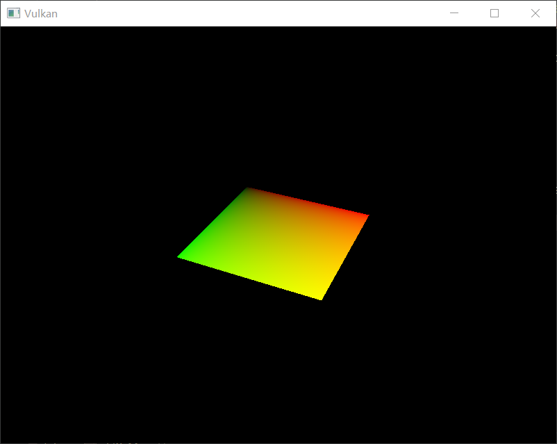
The green channel represents the horizontal coordinates and the red channel the vertical coordinates. The black and yellow corners confirm that the texture coordinates are correctly interpolated from 0, 0 to 1, 1 across the square. Visualizing data using colors is the shader programming equivalent of printf debugging, for lack of a better option!
A combined image sampler descriptor is represented in GLSL by a sampler uniform. Add a reference to it in the fragment shader:
layout(binding = 1) uniform sampler2D texSampler;
There are equivalent sampler1D and sampler3D types for other types of images. Make sure to use the correct binding here.
void main() {
outColor = texture(texSampler, fragTexCoord);
}
Textures are sampled using the built-in texture function. It takes a sampler and coordinate as arguments. The sampler automatically takes care of the filtering and transformations in the background. You should now see the texture on the square when you run the application:
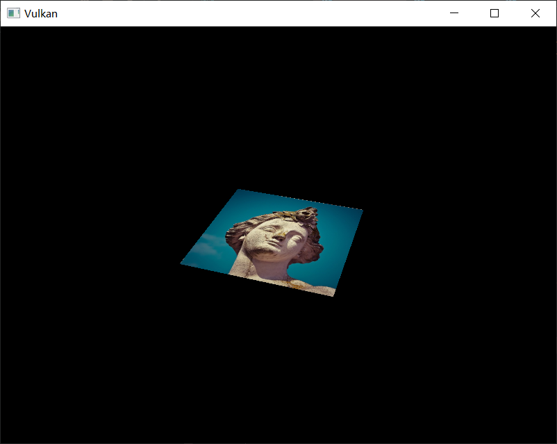
Try experimenting with the addressing modes by scaling the texture coordinates to values higher than 1. For example, the following fragment shader produces the result in the image below when using VK_SAMPLER_ADDRESS_MODE_REPEAT:
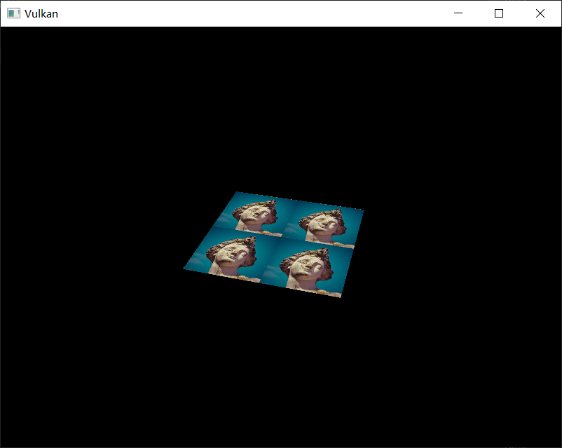
You can also manipulate the texture colors using the vertex colors:
void main() {
outColor = vec4(fragColor * texture(texSampler, fragTexCoord).rgb, 1.0);
}
I've separated the RGB and alpha channels here to not scale the alpha channel.
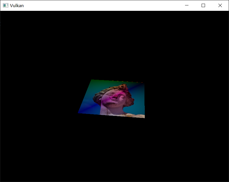
You now know how to access images in shaders! This is a very powerful technique when combined with images that are also written to in framebuffers. You can use these images as inputs to implement cool effects like post-processing and camera displays within the 3D world.
Combined image sampler
Introduction
We looked at descriptors for the first time in the uniform buffers part of the tutorial. In this chapter we will look at a new type of descriptor: combined image sampler. This descriptor makes it possible for shaders to access an image resource through a sampler object like the one we created in the previous chapter.
We'll start by modifying the descriptor layout, descriptor pool and descriptor set to include such a combined image sampler descriptor. After that, we're going to add texture coordinates to Vertex and modify the fragment shader to read colors from the texture instead of just interpolating the vertex colors.
Updating the descriptors
Browse to the createDescriptorSetLayout function and add a VkDescriptorSetLayoutBinding for a combined image sampler descriptor:
var bindings = VkDescriptorSetLayoutBinding.allocate(arena, 2);
var uboLayoutBinding = bindings[0];
uboLayoutBinding.binding(0);
uboLayoutBinding.descriptorType(VkDescriptorType.VK_DESCRIPTOR_TYPE_UNIFORM_BUFFER);
uboLayoutBinding.descriptorCount(1);
uboLayoutBinding.stageFlags(VkShaderStageFlags.VK_SHADER_STAGE_VERTEX_BIT);
uboLayoutBinding.pImmutableSamplers(null);
var samplerLayoutBinding = bindings[1];
samplerLayoutBinding.binding(1);
samplerLayoutBinding.descriptorCount(1);
samplerLayoutBinding.descriptorType(VkDescriptorType.VK_DESCRIPTOR_TYPE_COMBINED_IMAGE_SAMPLER);
samplerLayoutBinding.stageFlags(VkShaderStageFlags.VK_SHADER_STAGE_FRAGMENT_BIT);
var layoutInfo = VkDescriptorSetLayoutCreateInfo.allocate(arena);
layoutInfo.bindingCount(2);
layoutInfo.pBindings(bindings[0]);
Make sure to set the stageFlags to indicate that we intend to use the combined image sampler descriptor in the fragment shader. That's where the color of the fragment is going to be determined. It is possible to use texture sampling in the vertex shader, for example to dynamically deform a grid of vertices by a heightmap.
We must also create a larger descriptor pool to make room for the allocation of the combined image sampler by adding another VkPoolSize of type VK_DESCRIPTOR_TYPE_COMBINED_IMAGE_SAMPLER to the VkDescriptorPoolCreateInfo. Go to the createDescriptorPool function and modify it to include a VkDescriptorPoolSize for this descriptor:
var poolSizes = VkDescriptorPoolSize.allocate(arena, 2);
poolSizes[0].type(VkDescriptorType.VK_DESCRIPTOR_TYPE_UNIFORM_BUFFER);
poolSizes[0].descriptorCount(MAX_FRAMES_IN_FLIGHT);
poolSizes[1].type(VkDescriptorType.VK_DESCRIPTOR_TYPE_COMBINED_IMAGE_SAMPLER);
poolSizes[1].descriptorCount(MAX_FRAMES_IN_FLIGHT);
var poolInfo = VkDescriptorPoolCreateInfo.allocate(arena);
poolInfo.poolSizeCount(2);
poolInfo.pPoolSizes(poolSizes[0]);
poolInfo.maxSets(MAX_FRAMES_IN_FLIGHT);
Inadequate descriptor pools are a good example of a problem that the validation layers will not catch: As of Vulkan 1.1, vkAllocateDescriptorSets may fail with the error code VK_ERROR_POOL_OUT_OF_MEMORY if the pool is not sufficiently large, but the driver may also try to solve the problem internally. This means that sometimes (depending on hardware, pool size and allocation size) the driver will let us get away with an allocation that exceeds the limits of our descriptor pool. Other times, vkAllocateDescriptorSets will fail and return VK_ERROR_POOL_OUT_OF_MEMORY. This can be particularly frustrating if the allocation succeeds on some machines, but fails on others.
Since Vulkan shifts the responsiblity for the allocation to the driver, it is no longer a strict requirement to only allocate as many descriptors of a certain type (VK_DESCRIPTOR_TYPE_COMBINED_IMAGE_SAMPLER, etc.) as specified by the corresponding descriptorCount members for the creation of the descriptor pool. However, it remains best practise to do so, and in the future, VK_LAYER_KHRONOS_validation will warn about this type of problem if you enable Best Practice Validation.
The final step is to bind the actual image and sampler resources to the descriptors in the descriptor set. Go to the createDescriptorSets function.
for (int i = 0; i < MAX_FRAMES_IN_FLIGHT; i++) {
var bufferInfo = VkDescriptorBufferInfo.allocate(arena);
bufferInfo.buffer(uniformBuffers[i]);
bufferInfo.offset(0);
bufferInfo.range((long) UniformBufferObject.bufferSize() * Float.BYTES);
var imageInfo = VkDescriptorImageInfo.allocate(arena);
imageInfo.imageLayout(VkImageLayout.VK_IMAGE_LAYOUT_SHADER_READ_ONLY_OPTIMAL);
imageInfo.imageView(textureImageView);
imageInfo.sampler(textureSampler);
// ...
}
The resources for a combined image sampler structure must be specified in a VkDescriptorImageInfo struct, just like the buffer resource for a uniform buffer descriptor is specified in a VkDescriptorBufferInfo struct. This is where the objects from the previous chapter come together.
var descriptorWrites = VkWriteDescriptorSet.allocate(arena, 2);
descriptorWrites[0].dstSet(descriptorSets[i]);
descriptorWrites[0].dstBinding(0);
descriptorWrites[0].dstArrayElement(0);
descriptorWrites[0].descriptorType(VkDescriptorType.VK_DESCRIPTOR_TYPE_UNIFORM_BUFFER);
descriptorWrites[0].descriptorCount(1);
descriptorWrites[0].pBufferInfo(bufferInfo);
descriptorWrites[0].pImageInfo(null);
descriptorWrites[0].pTexelBufferView(null);
descriptorWrites[1].dstSet(descriptorSets[i]);
descriptorWrites[1].dstBinding(1);
descriptorWrites[1].dstArrayElement(0);
descriptorWrites[1].descriptorType(VkDescriptorType.VK_DESCRIPTOR_TYPE_COMBINED_IMAGE_SAMPLER);
descriptorWrites[1].descriptorCount(1);
descriptorWrites[1].pImageInfo(imageInfo);
deviceCommands.vkUpdateDescriptorSets(device, 2, descriptorWrites[0], 0, null);
The descriptors must be updated with this image info, just like the buffer. This time we're using the pImageInfo array instead of pBufferInfo. The descriptors are now ready to be used by the shaders!
Texture coordinates
There is one important ingredient for texture mapping that is still missing, and that's the actual coordinates for each vertex. The coordinates determine how the image is actually mapped to the geometry.
private static VkVertexInputBindingDescription getBindingDescription(Arena arena) {
var description = VkVertexInputBindingDescription.allocate(arena);
description.binding(0);
description.stride(Float.BYTES * 7); // 2 floats for position, 3 for color, 2 for texture coordinates
description.inputRate(VkVertexInputRate.VK_VERTEX_INPUT_RATE_VERTEX);
return description;
}
private static VkVertexInputAttributeDescription[] getAttributeDescriptions(Arena arena) {
var attributeDescriptions = VkVertexInputAttributeDescription.allocate(arena, 3);
attributeDescriptions[0].binding(0);
attributeDescriptions[0].location(0);
attributeDescriptions[0].format(VkFormat.VK_FORMAT_R32G32_SFLOAT);
attributeDescriptions[0].offset(0);
attributeDescriptions[1].binding(0);
attributeDescriptions[1].location(1);
attributeDescriptions[1].format(VkFormat.VK_FORMAT_R32G32B32_SFLOAT);
attributeDescriptions[1].offset(Float.BYTES * 2);
attributeDescriptions[2].binding(0);
attributeDescriptions[2].location(2);
attributeDescriptions[2].format(VkFormat.VK_FORMAT_R32G32_SFLOAT);
attributeDescriptions[2].offset(Float.BYTES * 5);
return attributeDescriptions;
}
Update the getBindingDescription and getAttributeDescriptions so that we can use access texture coordinates as input in the vertex shader. That is necessary to be able to pass them to the fragment shader for interpolation across the surface of the square.
private static final float[] VERTICES = {
// vec2 pos // vec3 color // vec2 texCoord
-0.5f, -0.5f, 1.0f, 0.0f, 0.0f, 1.0f, 0.0f,
0.5f, -0.5f, 0.0f, 1.0f, 0.0f, 0.0f, 0.0f,
0.5f, 0.5f, 0.0f, 0.0f, 1.0f, 0.0f, 1.0f,
-0.5f, 0.5f, 1.0f, 1.0f, 1.0f, 1.0f, 1.0f
};
In this tutorial, I will simply fill the square with the texture by using coordinates from 0, 0 in the top-left corner to 1, 1 in the bottom-right corner. Feel free to experiment with different coordinates. Try using coordinates below 0 or above 1 to see the addressing modes in action!
Shaders
The final step is modifying the shaders to sample colors from the texture. We first need to modify the vertex shader to pass through the texture coordinates to the fragment shader:
#version 450
layout(binding = 0) uniform UniformBufferObject {
mat4 model;
mat4 view;
mat4 proj;
} ubo;
layout(location = 0) in vec2 inPosition;
layout(location = 1) in vec3 inColor;
layout(location = 2) in vec2 inTexCoord;
layout(location = 0) out vec3 fragColor;
layout(location = 1) out vec2 fragTexCoord;
void main() {
gl_Position = ubo.proj * ubo.view * ubo.model * vec4(inPosition, 0.0, 1.0);
fragColor = inColor;
fragTexCoord = inTexCoord;
}
Just like the per vertex colors, the fragTexCoord values will be smoothly interpolated across the area of the square by the rasterizer. We can visualize this by having the fragment shader output the texture coordinates as colors:
#version 450
layout(location = 0) in vec3 fragColor;
layout(location = 1) in vec2 fragTexCoord;
layout(location = 0) out vec4 outColor;
void main() {
outColor = vec4(fragTexCoord, 0.0, 1.0);
}
Depth buffering
Introduction
The geometry we've worked with so far is projected into 3D, but it's still completely flat. In this chapter we're going to add a Z coordinate to the position to prepare for 3D meshes. We'll use this third coordinate to place a square over the current square to see a problem that arises when geometry is not sorted by depth.
3D geometry
Change the VERTICES array to use a 3D vector for the position:
private static final float[] VERTICES = {
// vec3 pos // vec3 color // vec2 texCoord
-0.5f, -0.5f, 0.0f, 1.0f, 0.0f, 0.0f, 1.0f, 0.0f,
0.5f, -0.5f, 0.0f, 0.0f, 1.0f, 0.0f, 0.0f, 0.0f,
0.5f, 0.5f, 0.0f, 0.0f, 0.0f, 1.0f, 0.0f, 1.0f,
-0.5f, 0.5f, 0.0f, 1.0f, 1.0f, 1.0f, 1.0f, 1.0f
};
Also change the VkVertexInputBindingDescription and VkVertexInputAttributeDescription to reflect the new vertex format:
private static VkVertexInputBindingDescription getBindingDescription(Arena arena) {
var description = VkVertexInputBindingDescription.allocate(arena);
description.binding(0);
description.stride(Float.BYTES * 8);
description.inputRate(VkVertexInputRate.VK_VERTEX_INPUT_RATE_VERTEX);
return description;
}
private static VkVertexInputAttributeDescription[] getAttributeDescriptions(Arena arena) {
var attributeDescriptions = VkVertexInputAttributeDescription.allocate(arena, 3);
attributeDescriptions[0].binding(0);
attributeDescriptions[0].location(0);
attributeDescriptions[0].format(VkFormat.VK_FORMAT_R32G32B32_SFLOAT);
attributeDescriptions[0].offset(0);
attributeDescriptions[1].binding(0);
attributeDescriptions[1].location(1);
attributeDescriptions[1].format(VkFormat.VK_FORMAT_R32G32B32_SFLOAT);
attributeDescriptions[1].offset(Float.BYTES * 3);
attributeDescriptions[2].binding(0);
attributeDescriptions[2].location(2);
attributeDescriptions[2].format(VkFormat.VK_FORMAT_R32G32_SFLOAT);
attributeDescriptions[2].offset(Float.BYTES * 6);
return attributeDescriptions;
}
Next, update the vertex shader to accept and transform 3D coordinates as input. Don't forget to recompile it afterwards!
layout(location = 0) in vec3 inPosition;
// ...
void main() {
gl_Position = ubo.proj * ubo.view * ubo.model * vec4(inPosition, 1.0);
fragColor = inColor;
fragTexCoord = inTexCoord;
}
If you run your application now, then you should see exactly the same result as before. It's time to add some extra geometry to make the scene more interesting, and to demonstrate the problem that we're going to tackle in this chapter. Duplicate the vertices to define positions for a square right under the current one like this:

Use Z coordinates of -0.5f and add the appropriate indices for the extra square:
private static final float[] VERTICES = {
// vec3 pos // vec3 color // vec2 texCoord
-0.5f, -0.5f, 0.0f, 1.0f, 0.0f, 0.0f, 1.0f, 0.0f,
0.5f, -0.5f, 0.0f, 0.0f, 1.0f, 0.0f, 0.0f, 0.0f,
0.5f, 0.5f, 0.0f, 0.0f, 0.0f, 1.0f, 0.0f, 1.0f,
-0.5f, 0.5f, 0.0f, 1.0f, 1.0f, 1.0f, 1.0f, 1.0f,
-0.5f, -0.5f, -0.5f, 1.0f, 0.0f, 0.0f, 1.0f, 0.0f,
0.5f, -0.5f, -0.5f, 0.0f, 1.0f, 0.0f, 0.0f, 0.0f,
0.5f, 0.5f, -0.5f, 0.0f, 0.0f, 1.0f, 0.0f, 1.0f,
-0.5f, 0.5f, -0.5f, 1.0f, 1.0f, 1.0f, 1.0f, 1.0f
};
private static final short[] INDICES = {
0, 1, 2,
2, 3, 0,
4, 5, 6,
6, 7, 4
};
Run your program now, and you'll see something resembling an Escher illustration:
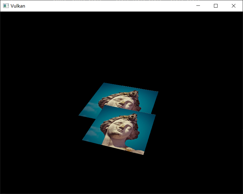
The problem is that the fragments of the lower square are drawn over the fragments of the upper square, simply because it comes later in the index array. There are two ways to solve this:
- Sort all the draw calls by depth from back to front
- Use depth testing with a depth buffer
The first approach is commonly used for drawing transparent objects, because order-independent transparency is a difficult challenge to solve. However, the problem of ordering fragments by depth is much more commonly solved using a depth buffer. A depth buffer is an additional attachment that stores the depth for every position, just like the color attachment stores the color of every position. Every time the rasterizer produces a fragment, the depth test will check if the new fragment is closer than the previous one. If it isn't, then the new fragment is discarded. A fragment that passes the depth test writes its own depth to the depth buffer. It is possible to manipulate this value from the fragment shader, just like you can manipulate the color output.
Depth image and view
A depth attachment is based on an image, just like the color attachment. The difference is that the swap chain will not automatically create depth images for us. We only need a single depth image, because only one draw operation is running at once. The depth image will again require the trifecta of resources: image, memory and image view.
private VkImage depthImage;
private VkDeviceMemory depthImageMemory;
private VkImageView depthImageView;
Create a new function createDepthResources to set up these resources:
private void initVulkan() {
// ...
createCommandPool();
createDepthResources();
createTextureImage();
// ...
}
// ...
private void createDepthResources() {
}
Creating a depth image is fairly straightforward. It should have the same resolution as the color attachment, defined by the swap chain extent, an image usage appropriate for a depth attachment, optimal tiling and device local memory. The only question is: what is the right format for a depth image? The format must contain a depth component, indicated by _D??_ in the VK_FORMAT_.
Unlike the texture image, we don't necessarily need a specific format, because we won't be directly accessing the texels from the program. It just needs to have a reasonable accuracy, at least 24 bits is common in real-world applications. There are several formats that fit this requirement:
VK_FORMAT_D32_SFLOAT: 32-bit float for depthVK_FORMAT_D32_SFLOAT_S8_UINT: 32-bit signed float for depth and 8 bit stencil componentVK_FORMAT_D24_UNORM_S8_UINT: 24-bit float for depth and 8 bit stencil component
The stencil component is used for stencil tests, which is an additional test that can be combined with depth testing. We'll look at this in a future chapter.
We could simply go for the VK_FORMAT_D32_SFLOAT format, because support for it is extremely common (see the hardware database), but it's nice to add some extra flexibility to our application where possible. We're going to write a function findSupportedFormat that takes a list of candidate formats in order from most desirable to least desirable, and checks which is the first one that is supported:
private @enumtype(VkFormat.class) int findSupportedFormat(
@enumtype(VkFormat.class) int[] candidates,
@enumtype(VkImageTiling.class) int tiling,
@enumtype(VkFormatFeatureFlags.class) int features
) {
}
The support of a format depends on the tiling mode and usage, so we must also include these as parameters. The support of a format can be queried using the vkGetPhysicalDeviceFormatProperties function:
for (var format : candidates) {
try (var arena = Arena.ofConfined()) {
var props = VkFormatProperties.allocate(arena);
instanceCommands.vkGetPhysicalDeviceFormatProperties(physicalDevice, format, props);
}
}
The VkFormatProperties struct contains three fields:
linearTilingFeatures: Use cases that are supported with linear tilingoptimalTilingFeatures: Use cases that are supported with optimal tilingbufferFeatures: Use cases that are supported for buffers
Only the first two are relevant here, and the one we check depends on the tiling parameter of the function:
if (tiling == VkImageTiling.VK_IMAGE_TILING_LINEAR && (props.linearTilingFeatures() & features) == features) {
return format;
}
else if (tiling == VkImageTiling.VK_IMAGE_TILING_OPTIMAL && (props.optimalTilingFeatures() & features) == features) {
return format;
}
If none of the candidate formats support the desired usage, then we can either return a special value or simply throw an exception:
private @enumtype(VkFormat.class) int findSupportedFormat(
@enumtype(VkFormat.class) int[] candidates,
@enumtype(VkImageTiling.class) int tiling,
@enumtype(VkFormatFeatureFlags.class) int features
) {
for (var format : candidates) {
try (var arena = Arena.ofConfined()) {
var props = VkFormatProperties.allocate(arena);
instanceCommands.vkGetPhysicalDeviceFormatProperties(physicalDevice, format, props);
if (tiling == VkImageTiling.VK_IMAGE_TILING_LINEAR && (props.linearTilingFeatures() & features) == features) {
return format;
}
else if (tiling == VkImageTiling.VK_IMAGE_TILING_OPTIMAL && (props.optimalTilingFeatures() & features) == features) {
return format;
}
}
}
throw new RuntimeException("Failed to find supported format");
}
We'll use this function now to create a findDepthFormat helper function to select a format with a depth component that supports usage as depth attachment:
private @enumtype(VkFormat.class) int findDepthFormat() {
return findSupportedFormat(
new int[] {
VkFormat.VK_FORMAT_D32_SFLOAT,
VkFormat.VK_FORMAT_D32_SFLOAT_S8_UINT,
VkFormat.VK_FORMAT_D24_UNORM_S8_UINT
},
VkImageTiling.VK_IMAGE_TILING_OPTIMAL,
VkFormatFeatureFlags.VK_FORMAT_FEATURE_DEPTH_STENCIL_ATTACHMENT_BIT
);
}
Make sure to use the VK_FORMAT_FEATURE_ flag instead of VK_IMAGE_USAGE_ in this case. All of these candidate formats contain a depth component, but the latter two also contain a stencil component. We won't be using that yet, but we do need to take that into account when performing layout transitions on images with these formats. Add a simple helper function that tells us if the chosen depth format contains a stencil component:
private boolean hasStencilComponent(@enumtype(VkFormat.class) int format) {
return format == VkFormat.VK_FORMAT_D32_SFLOAT_S8_UINT || format == VkFormat.VK_FORMAT_D24_UNORM_S8_UINT;
}
Call the function to find a depth format from createDepthResources:
var depthFormat = findDepthFormat();
We now have all the required information to invoke our createImage and createImageView helper functions:
var pair = createImage(
swapChainExtent.width(),
swapChainExtent.height(),
depthFormat,
VkImageTiling.VK_IMAGE_TILING_OPTIMAL,
VkImageUsageFlags.VK_IMAGE_USAGE_DEPTH_STENCIL_ATTACHMENT_BIT,
VkMemoryPropertyFlags.VK_MEMORY_PROPERTY_DEVICE_LOCAL_BIT
);
depthImage = pair.first;
depthImageMemory = pair.second;
depthImageView = createImageView(depthImage, depthFormat);
However, the createImageView function currently assumes that the subresource is always the VK_IMAGE_ASPECT_COLOR_BIT, so we will need to turn that field into a parameter:
private VkImageView createImageView(
VkImage image,
@enumtype(VkFormat.class) int format,
@enumtype(VkImageAspectFlags.class) int aspect
) {
// ...
subresourceRange.aspectMask(aspect);
// ...
}
Update all calls to this function to use the right aspect:
swapChainImageViews[i] = createImageView(
swapChainImages[i],
swapChainImageFormat,
VkImageAspectFlags.VK_IMAGE_ASPECT_COLOR_BIT
);
// ...
depthImageView = createImageView(depthImage, depthFormat, VkImageAspectFlags.VK_IMAGE_ASPECT_DEPTH_BIT);
// ...
textureImageView = createImageView(
textureImage,
VkFormat.VK_FORMAT_R8G8B8A8_SRGB,
VkImageAspectFlags.VK_IMAGE_ASPECT_COLOR_BIT
);
That's it for creating the depth image. We don't need to map it or copy another image to it, because we're going to clear it at the start of the render pass like the color attachment.
Explicitly transitioning the depth image
We don't need to explicitly transition the layout of the image to a depth attachment because we'll take care of this in the render pass. However, for completeness I'll still describe the process in this section. You may skip it if you like.
Make a call to transitionImageLayout at the end of the createDepthResources function like so:
transitionImageLayout(
depthImage,
depthFormat,
VkImageLayout.VK_IMAGE_LAYOUT_UNDEFINED,
VkImageLayout.VK_IMAGE_LAYOUT_DEPTH_STENCIL_ATTACHMENT_OPTIMAL
);
The undefined layout can be used as initial layout, because there are no existing depth image contents that matter. We need to update some of the logic in transitionImageLayout to use the right subresource aspect:
if (newLayout == VkImageLayout.VK_IMAGE_LAYOUT_DEPTH_STENCIL_ATTACHMENT_OPTIMAL) {
subResourceRange.aspectMask(VkImageAspectFlags.VK_IMAGE_ASPECT_DEPTH_BIT);
if (hasStencilComponent(format)) {
subResourceRange.aspectMask(subResourceRange.aspectMask()
| VkImageAspectFlags.VK_IMAGE_ASPECT_STENCIL_BIT);
}
}
else {
subResourceRange.aspectMask(VkImageAspectFlags.VK_IMAGE_ASPECT_COLOR_BIT);
}
Although we're not using the stencil component, we do need to include it in the layout transitions of the depth image.
Finally, add the correct access masks and pipeline stages:
// ...
else if (oldLayout == VkImageLayout.VK_IMAGE_LAYOUT_UNDEFINED
&& newLayout == VkImageLayout.VK_IMAGE_LAYOUT_DEPTH_STENCIL_ATTACHMENT_OPTIMAL) {
barrier.srcAccessMask(0);
barrier.dstAccessMask(VkAccessFlags.VK_ACCESS_DEPTH_STENCIL_ATTACHMENT_READ_BIT
| VkAccessFlags.VK_ACCESS_DEPTH_STENCIL_ATTACHMENT_WRITE_BIT);
sourceStage = VkPipelineStageFlags.VK_PIPELINE_STAGE_TOP_OF_PIPE_BIT;
destinationStage = VkPipelineStageFlags.VK_PIPELINE_STAGE_EARLY_FRAGMENT_TESTS_BIT;
}
// ...
The depth buffer will be read from to perform depth tests to see if a fragment is visible, and will be written to when a new fragment is drawn. The reading happens in the VK_PIPELINE_STAGE_EARLY_FRAGMENT_TESTS_BIT stage and the writing in the VK_PIPELINE_STAGE_LATE_FRAGMENT_TESTS_BIT. You should pick the earliest pipeline stage that matches the specified operations, so that it is ready for usage as depth attachment when it needs to be.
Render pass
We're now going to modify createRenderPass to include a depth attachment. First specify the VkAttachmentDescription:
var attachments = VkAttachmentDescription.allocate(arena, 2);
var colorAttachment = attachments[0];
// ...
var depthAttachment = attachments[1];
depthAttachment.format(findDepthFormat());
depthAttachment.samples(VkSampleCountFlags.VK_SAMPLE_COUNT_1_BIT);
depthAttachment.loadOp(VkAttachmentLoadOp.VK_ATTACHMENT_LOAD_OP_CLEAR);
depthAttachment.storeOp(VkAttachmentStoreOp.VK_ATTACHMENT_STORE_OP_DONT_CARE);
depthAttachment.stencilLoadOp(VkAttachmentLoadOp.VK_ATTACHMENT_LOAD_OP_DONT_CARE);
depthAttachment.stencilStoreOp(VkAttachmentStoreOp.VK_ATTACHMENT_STORE_OP_DONT_CARE);
depthAttachment.initialLayout(VkImageLayout.VK_IMAGE_LAYOUT_UNDEFINED);
depthAttachment.finalLayout(VkImageLayout.VK_IMAGE_LAYOUT_DEPTH_STENCIL_ATTACHMENT_OPTIMAL);
The format should be the same as the depth image itself. This time we don't care about storing the depth data (storeOp), because it will not be used after drawing has finished. This may allow the hardware to perform additional optimizations. Just like the color buffer, we don't care about the previous depth contents, so we can use VK_IMAGE_LAYOUT_UNDEFINED as initialLayout.
var depthAttachmentRef = VkAttachmentReference.allocate(arena);
depthAttachmentRef.attachment(1);
depthAttachmentRef.layout(VkImageLayout.VK_IMAGE_LAYOUT_DEPTH_STENCIL_ATTACHMENT_OPTIMAL);
Add a reference to the attachment for the first (and only) subpass:
var subpass = VkSubpassDescription.allocate(arena);
subpass.pipelineBindPoint(VkPipelineBindPoint.VK_PIPELINE_BIND_POINT_GRAPHICS);
subpass.colorAttachmentCount(1);
subpass.pColorAttachments(colorAttachmentRef);
subpass.pDepthStencilAttachment(depthAttachmentRef);
Unlike color attachments, a subpass can only use a single depth (+stencil) attachment. It wouldn't really make any sense to do depth tests on multiple buffers.
var renderPassInfo = VkRenderPassCreateInfo.allocate(arena);
renderPassInfo.attachmentCount(2);
renderPassInfo.pAttachments(attachments[0]);
renderPassInfo.subpassCount(1);
renderPassInfo.pSubpasses(subpass);
renderPassInfo.dependencyCount(1);
renderPassInfo.pDependencies(dependency);
Next, update the VkSubpassDependency struct to refer to both attachments.
var dependency = VkSubpassDependency.allocate(arena);
dependency.srcSubpass(Constants.VK_SUBPASS_EXTERNAL);
dependency.dstSubpass(0);
dependency.srcStageMask(VkPipelineStageFlags.VK_PIPELINE_STAGE_COLOR_ATTACHMENT_OUTPUT_BIT
| VkPipelineStageFlags.VK_PIPELINE_STAGE_EARLY_FRAGMENT_TESTS_BIT);
dependency.srcAccessMask(0);
dependency.dstStageMask(VkPipelineStageFlags.VK_PIPELINE_STAGE_COLOR_ATTACHMENT_OUTPUT_BIT
| VkPipelineStageFlags.VK_PIPELINE_STAGE_EARLY_FRAGMENT_TESTS_BIT);
dependency.dstAccessMask(VkAccessFlags.VK_ACCESS_COLOR_ATTACHMENT_WRITE_BIT
| VkAccessFlags.VK_ACCESS_DEPTH_STENCIL_ATTACHMENT_WRITE_BIT);
Finally, we need to extend our subpass dependencies to make sure that there is no conflict between the transitioning of the depth image and it being cleared as part of its load operation. The depth image is first accessed in the early fragment test pipeline stage and because we have a load operation that clears, we should specify the access mask for writes.
Framebuffer
The next step is to modify the framebuffer creation to bind the depth image to the depth attachment. Go to createFramebuffers and specify the depth image view as second attachment:
var pAttachments = VkImageView.Buffer.allocate(arena, 2);
pAttachments.write(0, swapChainImageViews[i]);
pAttachments.write(1, depthImageView);
var framebufferInfo = VkFramebufferCreateInfo.allocate(arena);
framebufferInfo.renderPass(renderPass);
framebufferInfo.attachmentCount(2);
framebufferInfo.pAttachments(pAttachments);
framebufferInfo.width(swapChainExtent.width());
framebufferInfo.height(swapChainExtent.height());
framebufferInfo.layers(1);
The color attachment differs for every swap chain image, but the same depth image can be used by all of them because only a single subpass is running at the same time due to our semaphores.
You'll also need to move the call to createFramebuffers to make sure that it is called after the depth image view has actually been created:
private void initVulkan() {
// ...
createDepthResources();
createFramebuffers();
// ...
}
Clear values
Because we now have multiple attachments with VK_ATTACHMENT_LOAD_OP_CLEAR, we also need to specify multiple clear values. Go to recordCommandBuffer and create an array of VkClearValue structs:
var pClearValue = VkClearValue.allocate(arena, 2);
pClearValue[0].color().float32().write(0, 0.0f);
pClearValue[0].color().float32().write(1, 0.0f);
pClearValue[0].color().float32().write(2, 0.0f);
pClearValue[0].color().float32().write(3, 1.0f);
pClearValue[1].depthStencil().depth(1.0f);
pClearValue[1].depthStencil().stencil(0);
renderPassInfo.clearValueCount(2);
renderPassInfo.pClearValues(pClearValue[0]);
The range of depths in the depth buffer is 0.0 to 1.0 in Vulkan, where 1.0 lies at the far view plane and 0.0 at the near view plane. The initial value at each point in the depth buffer should be the furthest possible depth, which is 1.0.
Note that the order of clearValues should be identical to the order of your attachments.
Depth and stencil state
The depth attachment is ready to be used now, but depth testing still needs to be enabled in the graphics pipeline. It is configured through the VkPipelineDepthStencilStateCreateInfo struct:
var depthStencil = VkPipelineDepthStencilStateCreateInfo.allocate(arena);
depthStencil.depthTestEnable(Constants.VK_TRUE);
depthStencil.depthWriteEnable(Constants.VK_TRUE);
The depthTestEnable field specifies if the depth of new fragments should be compared to the depth buffer to see if they should be discarded. The depthWriteEnable field specifies if the new depth of fragments that pass the depth test should actually be written to the depth buffer.
depthStencil.depthCompareOp(VkCompareOp.VK_COMPARE_OP_LESS);
The depthCompareOp field specifies the comparison that is performed to keep or discard fragments. We're sticking to the convention of lower depth = closer, so the depth of new fragments should be less.
depthStencil.depthBoundsTestEnable(Constants.VK_FALSE);
depthStencil.minDepthBounds(0.0f); // Optional
depthStencil.maxDepthBounds(1.0f); // Optional
The depthBoundsTestEnable, minDepthBounds and maxDepthBounds fields are used for the optional depth bound test. Basically, this allows you to only keep fragments that fall within the specified depth range. We won't be using this functionality.
depthStencil.stencilTestEnable(Constants.VK_FALSE);
The last field configures stencil buffer operations, which we also won't be using in this tutorial. If you want to use these operations, then you will have to make sure that the format of the depth/stencil image contains a stencil component.
pipelineInfo.pDepthStencilState(depthStencil);
Update the VkGraphicsPipelineCreateInfo struct to reference the depth stencil state we just filled in. A depth stencil state must always be specified if the render pass contains a depth stencil attachment.
If you run your program now, then you should see that the fragments of the geometry are now correctly ordered:
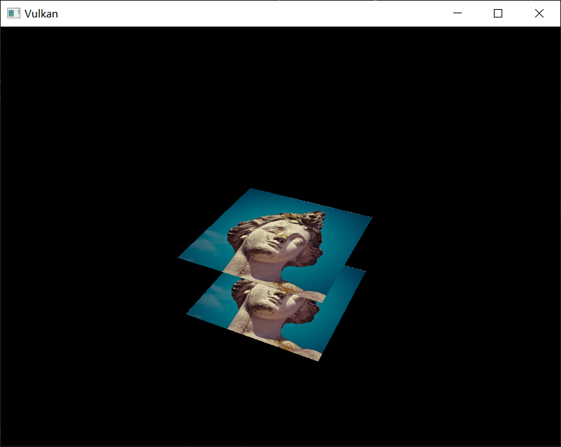
Handling window resize
The resolution of the depth buffer should change when the window is resized to match the new color attachment resolution. Extend the recreateSwapChain function to recreate the depth resources in that case:
private void recreateSwapChain() {
try (var arena = Arena.ofConfined()) {
var pWidth = IntBuffer.allocate(arena);
var pHeight = IntBuffer.allocate(arena);
glfw.glfwGetFramebufferSize(window, pWidth, pHeight);
while (pWidth.read() == 0 || pHeight.read() == 0) {
glfw.glfwGetFramebufferSize(window, pWidth, pHeight);
glfw.glfwWaitEvents();
}
}
deviceCommands.vkDeviceWaitIdle(device);
cleanupSwapChain();
createSwapchain();
createImageViews();
createDepthResources();
createFramebuffers();
}
The cleanup operations should happen in the swap chain cleanup function:
private void cleanupSwapChain() {
deviceCommands.vkDestroyImageView(device, depthImageView, null);
deviceCommands.vkDestroyImage(device, depthImage, null);
deviceCommands.vkFreeMemory(device, depthImageMemory, null);
// ...
}
Congratulations, your application is now finally ready to render arbitrary 3D geometry and have it look right. We're going to try this out in the next chapter by drawing a textured model!
Loading models
Introduction
Your program is now ready to render textured 3D meshes, but the current geometry in the vertices and indices arrays is not very interesting yet. In this chapter we're going to extend the program to load the vertices and indices from an actual model file to make the graphics card actually do some work.
Many graphics API tutorials have the reader write their own OBJ loader in a chapter like this. The problem with this is that any remotely interesting 3D application will soon require features that are not supported by this file format, like skeletal animation. We will load mesh data from an OBJ model in this chapter, but we'll focus more on integrating the mesh data with the program itself rather than the details of loading it from a file.
Sample mesh
In this chapter we won't be enabling lighting yet, so it helps to use a sample model that has lighting baked into the texture. An easy way to find such models is to look for 3D scans on Sketchfab. Many of the models on that site are available in OBJ format with a permissive license.
For this tutorial I've decided to go with the Viking room model by nigelgoh (CC BY 4.0). I tweaked the size and orientation of the model to use it as a drop in replacement for the current geometry:
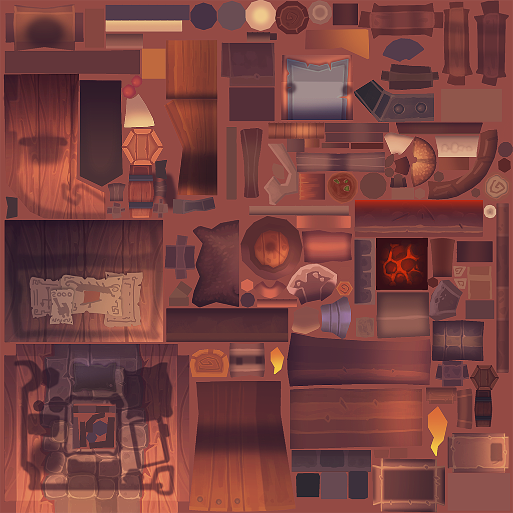
Feel free to use your own model, but make sure that it only consists of one material and that is has dimensions of about 1.5 x 1.5 x 1.5 units. If it is larger than that, then you'll have to change the view matrix. Put the model file in a new model directory next to shader and texture, and put the texture image in the texture directory.
Put two new configuration variables in your program to define the model and texture paths:
private static final String MODEL_PATH = "/model/viking_room.obj";
private static final String TEXTURE_PATH = "/texture/viking_room.png";
And update createTextureImage to use this path variable:
// ...
try (var stream = Application.class.getResourceAsStream(TEXTURE_PATH)) {
// ...
}
// ...
Loading vertices and indices
We're going to load the vertices and indices from the model file now, so we can remove the private static final VERTICES and INDICES arrays now. Replace them with two non-const class members, and update all references to them:
private float[] vertices;
private int[] indices;
private VkBuffer vertexBuffer;
private VkDeviceMemory vertexBufferMemory;
You should change the type of the indices from short to int, because there are going to be a lot more vertices than 32767. Remember to also change the vkCmdBindIndexBuffer parameter:
deviceCommands.vkCmdBindIndexBuffer(commandBuffer, indexBuffer, 0, VkIndexType.VK_INDEX_TYPE_UINT32);
And the bufferSize calculation in createIndexBuffer:
var bufferSize = indices.length * Integer.BYTES;
We're now going to write a loadModel function that uses the Obj library to populate the vertices and indices containers with the vertex data from the mesh. It should be called somewhere before the vertex and index buffers are created:
private void initVulkan() {
// ...
loadModel();
createVertexBuffer();
createIndexBuffer();
// ...
}
// ...
private void loadModel() {
}
A model is loaded into the library's data structures by calling the ObjReader.read static method:
private void loadModel() {
try (var stream = Application.class.getResourceAsStream("/model/viking_room.obj")) {
if (stream == null) {
throw new RuntimeException("Failed to load model");
}
var obj = ObjReader.read(stream);
}
catch (IOException e) {
throw new RuntimeException("Failed to load model", e);
}
}
An OBJ file consists of positions, normals, texture coordinates and faces. Faces consist of an arbitrary amount of vertices, where each vertex refers to a position, normal and/or texture coordinate by index. This makes it possible to not just reuse entire vertices, but also individual attributes.
Faces in OBJ files can actually contain an arbitrary number of vertices, whereas our application can only render triangles. Fortunately, the Obj library has a utility function that triangulates the faces for us:
obj = ObjUtils.convertToRenderable(obj);
This function also helps setting-up the indices array to reuse vertices, and flips UV coordinates to match the Vulkan/OpenGL texture coordinate system, so we don't need to do that on our own. We can now create the vertices and indices arrays:
indices = ObjData.getFaceVertexIndicesArray(obj);
var verticesArray = ObjData.getVerticesArray(obj);
var texCoordsArray = ObjData.getTexCoordsArray(obj, 2);
vertices = new float[obj.getNumVertices() * 8];
for (int i = 0; i < obj.getNumVertices(); i++) {
// vec3 pos
vertices[i * 8] = verticesArray[i * 3];
vertices[i * 8 + 1] = verticesArray[i * 3 + 1];
vertices[i * 8 + 2] = verticesArray[i * 3 + 2];
// vec3 color
vertices[i * 8 + 3] = 1.0f;
vertices[i * 8 + 4] = 1.0f;
vertices[i * 8 + 5] = 1.0f;
// vec2 texCoord
vertices[i * 8 + 6] = texCoordsArray[i * 2];
vertices[i * 8 + 7] = 1.0f - texCoordsArray[i * 2 + 1];
}
When you run your program, you should now see the correct result:

All that hard work is finally beginning to pay off with a demo like this!
As the model rotates you may notice that the rear (backside of the walls) looks a bit funny. This is normal and is simply because the model is not really designed to be viewed from that side.
Generating Mipmaps
Introduction
Our program can now load and render 3D models. In this chapter, we will add one more feature, mipmap generation. Mipmaps are widely used in games and rendering software, and Vulkan gives us complete control over how they are created.
Mipmaps are precalculated, downscaled versions of an image. Each new image is half the width and height of the previous one. Mipmaps are used as a form of Level of Detail or LOD. Objects that are far away from the camera will sample their textures from the smaller mip images. Using smaller images increases the rendering speed and avoids artifacts such as Moiré patterns. An example of what mipmaps look like:
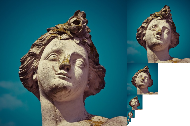
Image creation
In Vulkan, each of the mip images is stored in different mip levels of a VkImage. Mip level 0 is the original image, and the mip levels after level 0 are commonly referred to as the mip chain.
The number of mip levels is specified when the VkImage is created. Up until now, we have always set this value to one. We need to calculate the number of mip levels from the dimensions of the image. First, add a class member to store this number:
private int textureMipLevels;
private VkImage textureImage;
The value for textureMipLevels can be found once we've loaded the texture in createTextureImage:
textureMipLevels = (int) Math.floor(Math.log(Math.max(width, height)) / Math.log(2)) + 1;
Note: Java
Mathdoes not provide us alog2function, so we need to use the change of base logarithm formula to calculate the logarithm base 2.
This calculates the number of levels in the mip chain. The max function selects the largest dimension. The log function calculates how many times that dimension can be divided by 2. The floor function handles cases where the largest dimension is not a power of 2. 1 is added so that the original image has a mip level.
To use this value, we need to change the createImage, createImageView, and transitionImageLayout functions to allow us to specify the number of mip levels. Add a mipLevels parameter to the functions:
private Pair<VkImage, VkDeviceMemory> createImage(
int width,
int height,
int mipLevels,
@enumtype(VkFormat.class) int format,
@enumtype(VkImageTiling.class) int tiling,
@enumtype(VkImageUsageFlags.class) int usage,
@enumtype(VkMemoryPropertyFlags.class) int properties
) {
// ...
imageInfo.mipLevels(mipLevels);
// ...
}
private VkImageView createImageView(
VkImage image,
@enumtype(VkFormat.class) int format,
@enumtype(VkImageAspectFlags.class) int aspect,
int mipLevels
) {
// ...
subresourceRange.levelCount(mipLevels);
// ...
}
private void transitionImageLayout(
VkImage image,
@enumtype(VkFormat.class) int format,
@enumtype(VkImageLayout.class) int oldLayout,
@enumtype(VkImageLayout.class) int newLayout,
int mipLevels
) {
// ...
subResourceRange.levelCount(mipLevels);
// ...
}
Update all calls to these functions to use the right values:
var pair = createImage(
swapChainExtent.width(),
swapChainExtent.height(),
1,
depthFormat,
VkImageTiling.VK_IMAGE_TILING_OPTIMAL,
VkImageUsageFlags.VK_IMAGE_USAGE_DEPTH_STENCIL_ATTACHMENT_BIT,
VkMemoryPropertyFlags.VK_MEMORY_PROPERTY_DEVICE_LOCAL_BIT
);
depthImage = pair.first;
depthImageMemory = pair.second;
// ...
var pair2 = createImage(
width,
height,
textureMipLevels,
VkFormat.VK_FORMAT_R8G8B8A8_SRGB,
VkImageTiling.VK_IMAGE_TILING_OPTIMAL,
VkImageUsageFlags.VK_IMAGE_USAGE_TRANSFER_DST_BIT
| VkImageUsageFlags.VK_IMAGE_USAGE_SAMPLED_BIT,
VkMemoryPropertyFlags.VK_MEMORY_PROPERTY_DEVICE_LOCAL_BIT
);
textureImage = pair2.first;
textureImageMemory = pair2.second;
swapChainImageViews[i] = createImageView(
swapChainImages[i],
swapChainImageFormat,
VkImageAspectFlags.VK_IMAGE_ASPECT_COLOR_BIT
);
// ...
depthImageView = createImageView(depthImage, depthFormat, VkImageAspectFlags.VK_IMAGE_ASPECT_DEPTH_BIT, 1);
// ...
textureImageView = createImageView(
textureImage,
VkFormat.VK_FORMAT_R8G8B8A8_SRGB,
VkImageAspectFlags.VK_IMAGE_ASPECT_COLOR_BIT,
textureMipLevels
);
transitionImageLayout(
depthImage,
depthFormat,
VkImageLayout.VK_IMAGE_LAYOUT_UNDEFINED,
VkImageLayout.VK_IMAGE_LAYOUT_DEPTH_STENCIL_ATTACHMENT_OPTIMAL,
1
);
// ...
transitionImageLayout(
textureImage,
VkFormat.VK_FORMAT_R8G8B8A8_SRGB,
VkImageLayout.VK_IMAGE_LAYOUT_UNDEFINED,
VkImageLayout.VK_IMAGE_LAYOUT_TRANSFER_DST_OPTIMAL,
textureMipLevels
);
Generating Mipmaps
Our texture image now has multiple mip levels, but the staging buffer can only be used to fill mip level 0. The other levels are still undefined. To fill these levels we need to generate the data from the single level that we have. We will use the vkCmdBlitImage command. This command performs copying, scaling, and filtering operations. We will call this multiple times to blit data to each level of our texture image.
vkCmdBlitImage is considered a transfer operation, so we must inform Vulkan that we intend to use the texture image as both the source and destination of a transfer. Add VK_IMAGE_USAGE_TRANSFER_SRC_BIT to the texture image's usage flags in createTextureImage:
var pair2 = createImage(
width,
height,
textureMipLevels,
VkFormat.VK_FORMAT_R8G8B8A8_SRGB,
VkImageTiling.VK_IMAGE_TILING_OPTIMAL,
VkImageUsageFlags.VK_IMAGE_USAGE_TRANSFER_DST_BIT
| VkImageUsageFlags.VK_IMAGE_USAGE_SAMPLED_BIT
| VkImageUsageFlags.VK_IMAGE_USAGE_TRANSFER_SRC_BIT,
VkMemoryPropertyFlags.VK_MEMORY_PROPERTY_DEVICE_LOCAL_BIT
);
Like other image operations, vkCmdBlitImage depends on the layout of the image it operates on. We could transition the entire image to VK_IMAGE_LAYOUT_GENERAL, but this will most likely be slow. For optimal performance, the source image should be in VK_IMAGE_LAYOUT_TRANSFER_SRC_OPTIMAL and the destination image should be in VK_IMAGE_LAYOUT_TRANSFER_DST_OPTIMAL. Vulkan allows us to transition each mip level of an image independently. Each blit will only deal with two mip levels at a time, so we can transition each level into the optimal layout between blits commands.
transitionImageLayout only performs layout transitions on the entire image, so we'll need to write a few more pipeline barrier commands. Remove the existing transition to VK_IMAGE_LAYOUT_SHADER_READ_ONLY_OPTIMAL in createTextureImage:
// REMOVE this line from your createTextureImage function
//
// transitionImageLayout(
// textureImage,
// VkFormat.VK_FORMAT_R8G8B8A8_SRGB,
// VkImageLayout.VK_IMAGE_LAYOUT_TRANSFER_DST_OPTIMAL,
// VkImageLayout.VK_IMAGE_LAYOUT_SHADER_READ_ONLY_OPTIMAL,
// textureMipLevels
// );
This will leave each level of the texture image in VK_IMAGE_LAYOUT_TRANSFER_DST_OPTIMAL. Each level will be transitioned to VK_IMAGE_LAYOUT_SHADER_READ_ONLY_OPTIMAL after the blit command reading from it is finished.
We're now going to write the function that generates the mipmaps:
private void generateMipmaps(VkImage image, int texWidth, int texHeight, int mipLevels) {
try (var arena = Arena.ofConfined()) {
var commandBuffer = beginSingleTimeCommands();
var barrier = VkImageMemoryBarrier.allocate(arena);
barrier.image(image);
barrier.srcQueueFamilyIndex(Constants.VK_QUEUE_FAMILY_IGNORED);
barrier.dstQueueFamilyIndex(Constants.VK_QUEUE_FAMILY_IGNORED);
barrier.subresourceRange().aspectMask(VkImageAspectFlags.VK_IMAGE_ASPECT_COLOR_BIT);
barrier.subresourceRange().baseArrayLayer(0);
barrier.subresourceRange().layerCount(1);
barrier.subresourceRange().levelCount(1);
var blit = VkImageBlit.allocate(arena);
endSingleTimeCommands(commandBuffer);
}
}
We're going to make several transitions, so we'll reuse this VkImageMemoryBarrier. The fields set above will remain the same for all barriers. subresourceRange.miplevel, oldLayout, newLayout, srcAccessMask, and dstAccessMask will be changed for each transition. We also pre-allocate a VkImageBlit struct so we don't reallocate it for each blit, we'll see that soon.
var mipWidth = texWidth;
var mipHeight = texHeight;
for (var i = 1; i < mipLevels; i++) {
}
This loop will record each of the VkCmdBlitImage commands. Note that the loop variable starts at 1, not 0.
barrier.subresourceRange().baseMipLevel(i - 1);
barrier.oldLayout(VkImageLayout.VK_IMAGE_LAYOUT_TRANSFER_DST_OPTIMAL);
barrier.newLayout(VkImageLayout.VK_IMAGE_LAYOUT_TRANSFER_SRC_OPTIMAL);
barrier.srcAccessMask(VkAccessFlags.VK_ACCESS_TRANSFER_WRITE_BIT);
barrier.dstAccessMask(VkAccessFlags.VK_ACCESS_TRANSFER_READ_BIT);
deviceCommands.vkCmdPipelineBarrier(
commandBuffer,
VkPipelineStageFlags.VK_PIPELINE_STAGE_TRANSFER_BIT,
VkPipelineStageFlags.VK_PIPELINE_STAGE_TRANSFER_BIT,
0,
0, null,
0, null,
1, barrier
);
First, we transition level i - 1 to VK_IMAGE_LAYOUT_TRANSFER_SRC_OPTIMAL. This transition will wait for level i - 1 to be filled, either from the previous blit command, or from vkCmdCopyBufferToImage. The current blit command will wait on this transition.
var srcOffsets = blit.srcOffsets();
srcOffsets[0].x(0);
srcOffsets[0].y(0);
srcOffsets[0].z(0);
srcOffsets[1].x(mipWidth);
srcOffsets[1].y(mipHeight);
srcOffsets[1].z(1);
var srcSubresource = blit.srcSubresource();
srcSubresource.aspectMask(VkImageAspectFlags.VK_IMAGE_ASPECT_COLOR_BIT);
srcSubresource.mipLevel(i - 1);
srcSubresource.baseArrayLayer(0);
srcSubresource.layerCount(1);
var dstOffsets = blit.dstOffsets();
dstOffsets[0].x(0);
dstOffsets[0].y(0);
dstOffsets[0].z(0);
dstOffsets[1].x(mipWidth > 1 ? mipWidth / 2 : 1);
dstOffsets[1].y(mipHeight > 1 ? mipHeight / 2 : 1);
dstOffsets[1].z(1);
var dstSubresource = blit.dstSubresource();
dstSubresource.aspectMask(VkImageAspectFlags.VK_IMAGE_ASPECT_COLOR_BIT);
dstSubresource.mipLevel(i);
dstSubresource.baseArrayLayer(0);
dstSubresource.layerCount(1);
Next, we specify the regions that will be used in the blit operation. The source mip level is i - 1 and the destination mip level is i. The two elements of the srcOffsets array determine the 3D region that data will be blitted from. dstOffsets determines the region that data will be blitted to. The X and Y dimensions of the dstOffsets[1] are divided by two since each mip level is half the size of the previous level. The Z dimension of srcOffsets[1] and dstOffsets[1] must be 1, since a 2D image has a depth of 1.
deviceCommands.vkCmdBlitImage(
commandBuffer,
image,
VkImageLayout.VK_IMAGE_LAYOUT_TRANSFER_SRC_OPTIMAL,
image,
VkImageLayout.VK_IMAGE_LAYOUT_TRANSFER_DST_OPTIMAL,
1,
blit,
VkFilter.VK_FILTER_LINEAR
);
Now, we record the blit command. Note that textureImage is used for both the srcImage and dstImage parameter. This is because we're blitting between different levels of the same image. The source mip level was just transitioned to VK_IMAGE_LAYOUT_TRANSFER_SRC_OPTIMAL and the destination level is still in VK_IMAGE_LAYOUT_TRANSFER_DST_OPTIMAL from createTextureImage.
Beware if you are using a dedicated transfer queue (as suggested in Vertex buffers): vkCmdBlitImage must be submitted to a queue with graphics capability.
The last parameter allows us to specify a VkFilter to use in the blit. We have the same filtering options here that we had when making the VkSampler. We use the VK_FILTER_LINEAR to enable interpolation.
barrier.oldLayout(VkImageLayout.VK_IMAGE_LAYOUT_TRANSFER_SRC_OPTIMAL);
barrier.newLayout(VkImageLayout.VK_IMAGE_LAYOUT_SHADER_READ_ONLY_OPTIMAL);
barrier.srcAccessMask(VkAccessFlags.VK_ACCESS_TRANSFER_READ_BIT);
barrier.dstAccessMask(VkAccessFlags.VK_ACCESS_SHADER_READ_BIT);
deviceCommands.vkCmdPipelineBarrier(
commandBuffer,
VkPipelineStageFlags.VK_PIPELINE_STAGE_TRANSFER_BIT,
VkPipelineStageFlags.VK_PIPELINE_STAGE_FRAGMENT_SHADER_BIT,
0,
0, null,
0, null,
1, barrier
);
This barrier transitions mip level i - 1 to VK_IMAGE_LAYOUT_SHADER_READ_ONLY_OPTIMAL. This transition waits on the current blit command to finish. All sampling operations will wait on this transition to finish.
if (mipWidth > 1) {
mipWidth /= 2;
}
if (mipHeight > 1) {
mipHeight /= 2;
}
At the end of the loop, we divide the current mip dimensions by two. We check each dimension before the division to ensure that dimension never becomes 0. This handles cases where the image is not square, since one of the mip dimensions would reach 1 before the other dimension. When this happens, that dimension should remain 1 for all remaining levels.
barrier.subresourceRange().baseMipLevel(mipLevels - 1);
barrier.oldLayout(VkImageLayout.VK_IMAGE_LAYOUT_TRANSFER_DST_OPTIMAL);
barrier.newLayout(VkImageLayout.VK_IMAGE_LAYOUT_SHADER_READ_ONLY_OPTIMAL);
barrier.srcAccessMask(VkAccessFlags.VK_ACCESS_TRANSFER_WRITE_BIT);
barrier.dstAccessMask(VkAccessFlags.VK_ACCESS_SHADER_READ_BIT);
deviceCommands.vkCmdPipelineBarrier(
commandBuffer,
VkPipelineStageFlags.VK_PIPELINE_STAGE_TRANSFER_BIT,
VkPipelineStageFlags.VK_PIPELINE_STAGE_FRAGMENT_SHADER_BIT,
0,
0, null,
0, null,
1, barrier
);
Before we end the command buffer, we insert one more pipeline barrier. This barrier transitions the last mip level from VK_IMAGE_LAYOUT_TRANSFER_DST_OPTIMAL to VK_IMAGE_LAYOUT_SHADER_READ_ONLY_OPTIMAL. This wasn't handled by the loop, since the last mip level is never blitted from.
Finally, add the call to generateMipmaps in createTextureImage:
// transitionImageLayout
// copyBufferToImage
generateMipmaps(textureImage, width, height, textureMipLevels);
Our texture image's mipmaps are now completely filled.
Linear filtering support
It is very convenient to use a built-in function like vkCmdBlitImage to generate all the mip levels, but unfortunately it is not guaranteed to be supported on all platforms. It requires the texture image format we use to support linear filtering, which can be checked with the vkGetPhysicalDeviceFormatProperties function. We will add a check to the generateMipmaps function for this.
First add one additional parameter that specifies the image format:
generateMipmaps(textureImage, VkFormat.VK_FORMAT_R8G8B8A8_SRGB, width, height, textureMipLevels);
// ...
private void generateMipmaps(
VkImage image,
@enumtype(VkFormat.class) int imageFormat,
int texWidth,
int texHeight,
int mipLevels
) {
// ...
}
In the generateMipmaps function, use vkGetPhysicalDeviceFormatProperties to request the properties of the texture image format:
private void generateMipmaps(
VkImage image,
@enumtype(VkFormat.class) int imageFormat,
int texWidth,
int texHeight,
int mipLevels
) {
try (var arena = Arena.ofConfined()) {
var formatProperties = VkFormatProperties.allocate(arena);
instanceCommands.vkGetPhysicalDeviceFormatProperties(physicalDevice, imageFormat, formatProperties);
// ...
}
}
The VkFormatProperties struct has three fields named linearTilingFeatures, optimalTilingFeatures and bufferFeatures that each describe how the format can be used depending on the way it is used. We create a texture image with the optimal tiling format, so we need to check optimalTilingFeatures. Support for the linear filtering feature can be checked with the VK_FORMAT_FEATURE_SAMPLED_IMAGE_FILTER_LINEAR_BIT:
if ((formatProperties.optimalTilingFeatures() & VkFormatFeatureFlags.VK_FORMAT_FEATURE_SAMPLED_IMAGE_FILTER_LINEAR_BIT) == 0) {
throw new RuntimeException("Texture image format does not support linear blitting");
}
There are two alternatives in this case. You could implement a function that searches common texture image formats for one that does support linear blitting, or you could implement the mipmap generation in software with a library like stb_image_resize. Each mip level can then be loaded into the image in the same way that you loaded the original image.
It should be noted that it is uncommon in practice to generate the mipmap levels at runtime anyway. Usually they are pregenerated and stored in the texture file alongside the base level to improve loading speed. Implementing resizing in software and loading multiple levels from a file is left as an exercise to the reader.
Sampler
While the VkImage holds the mipmap data, VkSampler controls how that data is read while rendering. Vulkan allows us to specify minLod, maxLod, mipLodBias, and mipmapMode ("Lod" means "Level of Detail"). When a texture is sampled, the sampler selects a mip level according to the following pseudocode:
lod = getLodLevelFromScreenSize(); //smaller when the object is close, may be negative
lod = clamp(lod + mipLodBias, minLod, maxLod);
level = clamp(floor(lod), 0, texture.mipLevels - 1); //clamped to the number of mip levels in the texture
if (mipmapMode == VK_SAMPLER_MIPMAP_MODE_NEAREST) {
color = sample(level);
} else {
color = blend(sample(level), sample(level + 1));
}
If samplerInfo.mipmapMode is VK_SAMPLER_MIPMAP_MODE_NEAREST, lod selects the mip level to sample from. If the mipmap mode is VK_SAMPLER_MIPMAP_MODE_LINEAR, lod is used to select two mip levels to be sampled. Those levels are sampled and the results are linearly blended.
The sample operation is also affected by lod:
if (lod <= 0) {
color = readTexture(uv, magFilter);
} else {
color = readTexture(uv, minFilter);
}
If the object is close to the camera, magFilter is used as the filter. If the object is further from the camera, minFilter is used. Normally, lod is non-negative, and is only 0 when close the camera. mipLodBias lets us force Vulkan to use lower lod and level than it would normally use.
To see the results of this chapter, we need to choose values for our textureSampler. We've already set the minFilter and magFilter to use VK_FILTER_LINEAR. We just need to choose values for minLod, maxLod, mipLodBias, and mipmapMode.
private void createTextureSampler() {
// ...
samplerInfo.mipmapMode(VkSamplerMipmapMode.VK_SAMPLER_MIPMAP_MODE_LINEAR);
samplerInfo.minLod(0.0f); // Optional
samplerInfo.maxLod((float) textureMipLevels);
samplerInfo.mipLodBias(0.0f); // Optional
}
To allow the full range of mip levels to be used, we set minLod to 0.0f, and maxLod to the number of mip levels. We have no reason to change the lod value , so we set mipLodBias to 0.0f.
Now run your program and you should see the following:

It's not a dramatic difference, since our scene is so simple. There are subtle differences if you look closely.
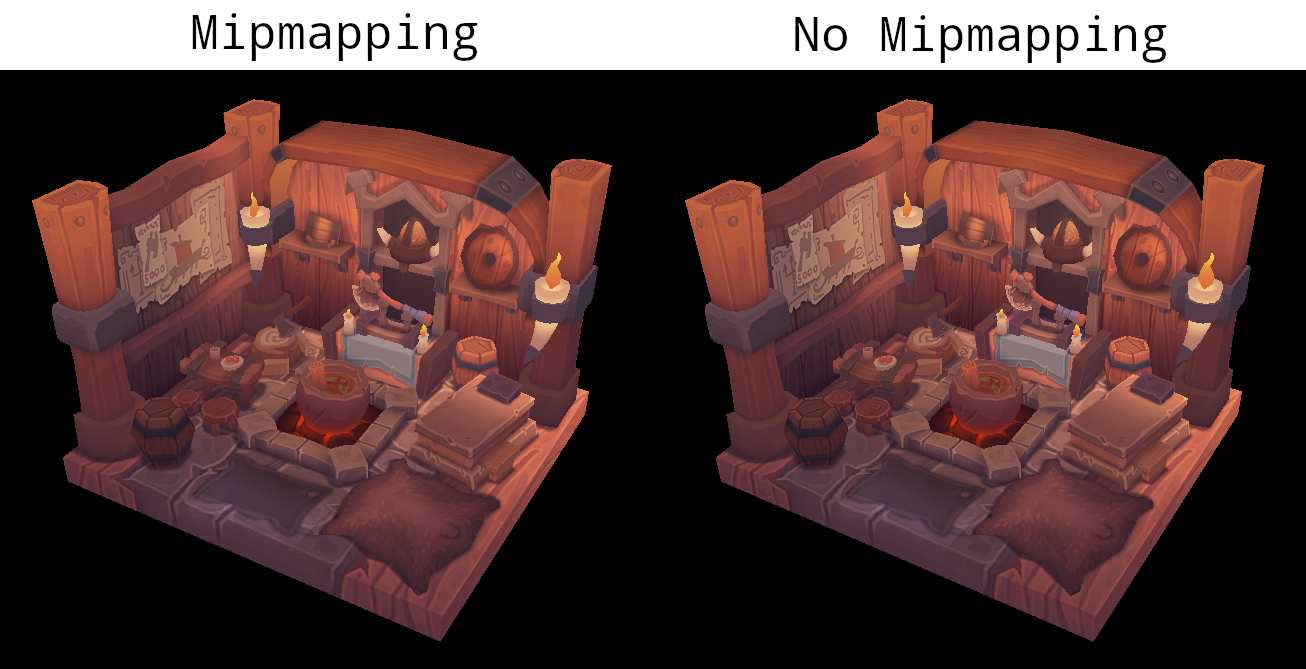
The most noticeable difference is the writing on the papers. With mipmaps, the writing has been smoothed. Without mipmaps, the writing has harsh edges and gaps from Moiré artifacts.
You can play around with the sampler settings to see how they affect mipmapping. For example, by changing minLod, you can force the sampler to not use the lowest mip levels:
samplerInfo.minLod(textureMipLevels / 2.0f);
These settings will produce this image:
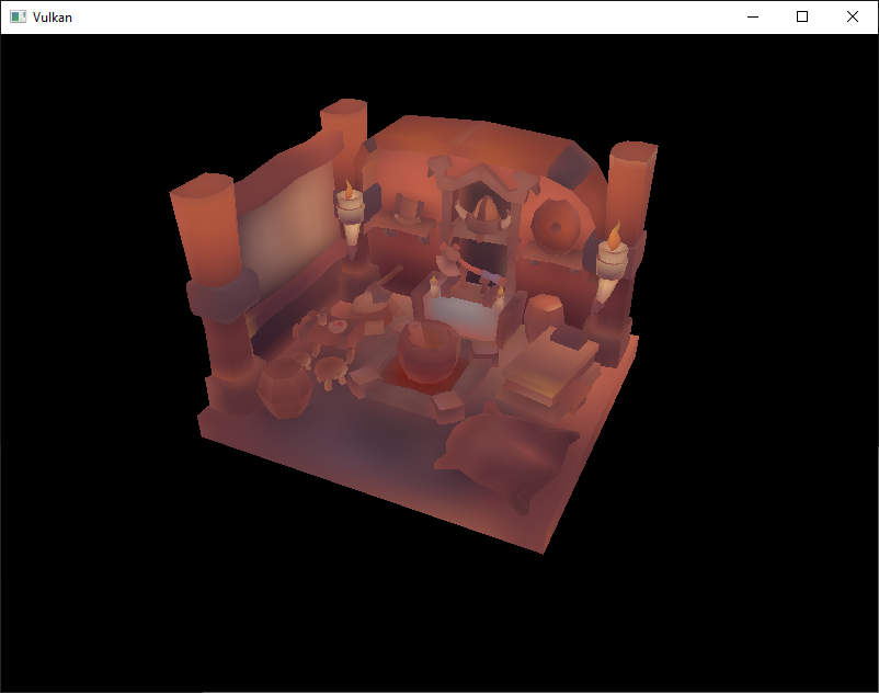
This is how higher mip levels will be used when objects are further away from the camera.
Multisampling
Introduction
Our program can now load multiple levels of detail for textures which fixes artifacts when rendering objects far away from the viewer. The image is now a lot smoother, however on closer inspection you will notice jagged saw-like patterns along the edges of drawn geometric shapes. This is especially visible in one of our early programs when we rendered a quad:

This undesired effect is called "aliasing" and it's a result of a limited numbers of pixels that are available for rendering. Since there are no displays out there with unlimited resolution, it will be always visible to some extent. There's a number of ways to fix this and in this chapter we'll focus on one of the more popular ones: Multisample antialiasing (MSAA).
In ordinary rendering, the pixel color is determined based on a single sample point which in most cases is the center of the target pixel on screen. If part of the drawn line passes through a certain pixel but doesn't cover the sample point, that pixel will be left blank, leading to the jagged "staircase" effect.
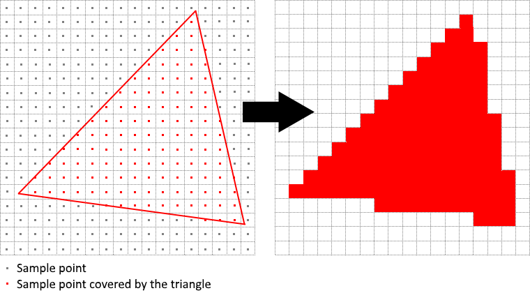
What MSAA does is it uses multiple sample points per pixel (hence the name) to determine its final color. As one might expect, more samples lead to better results, however it is also more computationally expensive.
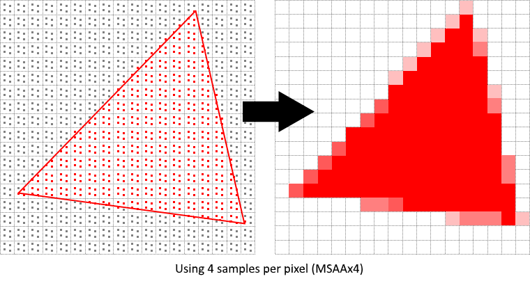
In our implementation, we will focus on using the maximum available sample count. Depending on your application this may not always be the best approach and it might be better to use less samples for the sake of higher performance if the final result meets your quality demands.
Getting available sample count
Let's start off by determining how many samples our hardware can use. Most modern GPUs support at least 8 samples but this number is not guaranteed to be the same everywhere. We'll keep track of it by adding a new class member:
private @enumtype(VkSampleCountFlags.class) int msaaSamples;
By default, we'll be using only one sample per pixel which is equivalent to no multisampling, in which case the final image will remain unchanged. The exact maximum number of samples can be extracted from VkPhysicalDeviceProperties associated with our selected physical device. We're using a depth buffer, so we have to take into account the sample count for both color and depth. The highest sample count that is supported by both (&) will be the maximum we can support. Add a function that will fetch this information for us:By default we'll be using only one sample per pixel which is equivalent to no multisampling, in which case the final image will remain unchanged. The exact maximum number of samples can be extracted from VkPhysicalDeviceProperties associated with our selected physical device. We're using a depth buffer, so we have to take into account the sample count for both color and depth. The highest sample count that is supported by both (&) will be the maximum we can support. Add a function that will fetch this information for us:
private @enumtype(VkSampleCountFlags.class) int getMaxUsableSampleCount() {
try (var arena = Arena.ofConfined()) {
var physicalDeviceProperties = VkPhysicalDeviceProperties.allocate(arena);
instanceCommands.vkGetPhysicalDeviceProperties(physicalDevice, physicalDeviceProperties);
var counts = physicalDeviceProperties.limits().framebufferColorSampleCounts()
& physicalDeviceProperties.limits().framebufferDepthSampleCounts();
if ((counts & VkSampleCountFlags.VK_SAMPLE_COUNT_64_BIT) != 0) {
return VkSampleCountFlags.VK_SAMPLE_COUNT_64_BIT;
}
if ((counts & VkSampleCountFlags.VK_SAMPLE_COUNT_32_BIT) != 0) {
return VkSampleCountFlags.VK_SAMPLE_COUNT_32_BIT;
}
if ((counts & VkSampleCountFlags.VK_SAMPLE_COUNT_16_BIT) != 0) {
return VkSampleCountFlags.VK_SAMPLE_COUNT_16_BIT;
}
if ((counts & VkSampleCountFlags.VK_SAMPLE_COUNT_8_BIT) != 0) {
return VkSampleCountFlags.VK_SAMPLE_COUNT_8_BIT;
}
if ((counts & VkSampleCountFlags.VK_SAMPLE_COUNT_4_BIT) != 0) {
return VkSampleCountFlags.VK_SAMPLE_COUNT_4_BIT;
}
if ((counts & VkSampleCountFlags.VK_SAMPLE_COUNT_2_BIT) != 0) {
return VkSampleCountFlags.VK_SAMPLE_COUNT_2_BIT;
}
return VkSampleCountFlags.VK_SAMPLE_COUNT_1_BIT;
}
}
We will now use this function to set the msaaSamples variable during the physical device selection process. For this, we have to slightly modify the pickPhysicalDevice function:
private void pickPhysicalDevice() {
// ...
for (var device : devices) {
if (isDeviceSuitable(device)) {
physicalDevice = device;
msaaSamples = getMaxUsableSampleCount();
break;
}
}
// ...
}
Setting up a render target
In MSAA, each pixel is sampled in an offscreen buffer which is then rendered to the screen. This new buffer is slightly different from regular images we've been rendering to - they have to be able to store more than one sample per pixel. Once a multisampled buffer is created, it has to be resolved to the default framebuffer (which stores only a single sample per pixel). This is why we have to create an additional render target and modify our current drawing process. We only need one render target since only one drawing operation is active at a time, just like with the depth buffer. Add the following class members:
private VkImage colorImage;
private VkDeviceMemory colorImageMemory;
private VkImageView colorImageView;
This new image will have to store the desired number of samples per pixel, so we need to pass this number to VkImageCreateInfo during the image creation process. Modify the createImage function by adding a numSamples parameter:
private Pair<VkImage, VkDeviceMemory> createImage(
int width,
int height,
int mipLevels,
@enumtype(VkSampleCountFlags.class) int numSamples,
@enumtype(VkFormat.class) int format,
@enumtype(VkImageTiling.class) int tiling,
@enumtype(VkImageUsageFlags.class) int usage,
@enumtype(VkMemoryPropertyFlags.class) int properties
) {
// ...
imageInfo.samples(numSamples);
// ...
}
For now, update all calls to this function using VK_SAMPLE_COUNT_1_BIT - we will be replacing this with proper values as we progress with implementation:
var pair = createImage(
swapChainExtent.width(),
swapChainExtent.height(),
1,
VkSampleCountFlags.VK_SAMPLE_COUNT_1_BIT,
depthFormat,
VkImageTiling.VK_IMAGE_TILING_OPTIMAL,
VkImageUsageFlags.VK_IMAGE_USAGE_DEPTH_STENCIL_ATTACHMENT_BIT,
VkMemoryPropertyFlags.VK_MEMORY_PROPERTY_DEVICE_LOCAL_BIT
);
depthImage = pair.first;
depthImageMemory = pair.second;
// ...
var pair2 = createImage(
width,
height,
textureMipLevels,
VkSampleCountFlags.VK_SAMPLE_COUNT_1_BIT,
VkFormat.VK_FORMAT_R8G8B8A8_SRGB,
VkImageTiling.VK_IMAGE_TILING_OPTIMAL,
VkImageUsageFlags.VK_IMAGE_USAGE_TRANSFER_DST_BIT
| VkImageUsageFlags.VK_IMAGE_USAGE_SAMPLED_BIT
| VkImageUsageFlags.VK_IMAGE_USAGE_TRANSFER_SRC_BIT,
VkMemoryPropertyFlags.VK_MEMORY_PROPERTY_DEVICE_LOCAL_BIT
);
textureImage = pair2.first;
textureImageMemory = pair2.second;
We will now create a multisampled color buffer. Add a createColorResources function and note that we're using msaaSamples here as a function parameter to createImage. We're also using only one mip level, since this is enforced by the Vulkan specification in case of images with more than one sample per pixel. Also, this color buffer doesn't need mipmaps since it's not going to be used as a texture:
private void createColorResources() {
var colorFormat = swapChainImageFormat;
var pair = createImage(
swapChainExtent.width(),
swapChainExtent.height(),
1,
msaaSamples,
colorFormat,
VkImageTiling.VK_IMAGE_TILING_OPTIMAL,
VkImageUsageFlags.VK_IMAGE_USAGE_TRANSIENT_ATTACHMENT_BIT
| VkImageUsageFlags.VK_IMAGE_USAGE_COLOR_ATTACHMENT_BIT,
VkMemoryPropertyFlags.VK_MEMORY_PROPERTY_DEVICE_LOCAL_BIT
);
colorImage = pair.first;
colorImageMemory = pair.second;
colorImageView = createImageView(colorImage, colorFormat, VkImageAspectFlags.VK_IMAGE_ASPECT_COLOR_BIT, 1);
}
For consistency, call the function right before createDepthResources:
private void initVulkan() {
// ...
createColorResources();
createDepthResources();
// ...
}
Now that we have a multisampled color buffer in place it's time to take care of depth. Modify createDepthResources and update the number of samples used by the depth buffer:
var pair = createImage(
swapChainExtent.width(),
swapChainExtent.height(),
1,
msaaSamples,
depthFormat,
VkImageTiling.VK_IMAGE_TILING_OPTIMAL,
VkImageUsageFlags.VK_IMAGE_USAGE_DEPTH_STENCIL_ATTACHMENT_BIT,
VkMemoryPropertyFlags.VK_MEMORY_PROPERTY_DEVICE_LOCAL_BIT
);
We have now created a couple of new Vulkan resources, so let's not forget to release them when necessary:
private void cleanupSwapChain() {
deviceCommands.vkDestroyImageView(device, colorImageView, null);
deviceCommands.vkDestroyImage(device, colorImage, null);
deviceCommands.vkFreeMemory(device, colorImageMemory, null);
// ...
}
And update the recreateSwapChain so that the new color image can be recreated in the correct resolution when the window is resized:
private void recreateSwapChain() {
// ...
createImageViews();
createColorResources();
createDepthResources();
// ...
}
We made it past the initial MSAA setup, now we need to start using this new resource in our graphics pipeline, framebuffer, render pass and see the results!
Adding new attachments
Let's take care of the render pass first. Modify createRenderPass and update color and depth attachment creation info structs:
private void createRenderPass() {
// ...
colorAttachment.samples(msaaSamples);
colorAttachment.finalLayout(VkImageLayout.VK_IMAGE_LAYOUT_COLOR_ATTACHMENT_OPTIMAL);
// ...
depthAttachment.samples(msaaSamples);
// ...
}
You'll notice that we have changed the finalLayout from VK_IMAGE_LAYOUT_PRESENT_SRC_KHR to VK_IMAGE_LAYOUT_COLOR_ATTACHMENT_OPTIMAL. That's because multisampled images cannot be presented directly. We first need to resolve them to a regular image. This requirement does not apply to the depth buffer, since it won't be presented at any point. Therefore, we will have to add only one new attachment for color which is a so-called resolve attachment:
var attachments = VkAttachmentDescription.allocate(arena, 3);
// ...
var colorAttachmentResolve = attachments[2];
colorAttachmentResolve.format(swapChainImageFormat);
colorAttachmentResolve.samples(VkSampleCountFlags.VK_SAMPLE_COUNT_1_BIT);
colorAttachmentResolve.loadOp(VkAttachmentLoadOp.VK_ATTACHMENT_LOAD_OP_DONT_CARE);
colorAttachmentResolve.storeOp(VkAttachmentStoreOp.VK_ATTACHMENT_STORE_OP_STORE);
colorAttachmentResolve.stencilLoadOp(VkAttachmentLoadOp.VK_ATTACHMENT_LOAD_OP_DONT_CARE);
colorAttachmentResolve.stencilStoreOp(VkAttachmentStoreOp.VK_ATTACHMENT_STORE_OP_DONT_CARE);
colorAttachmentResolve.initialLayout(VkImageLayout.VK_IMAGE_LAYOUT_UNDEFINED);
colorAttachmentResolve.finalLayout(VkImageLayout.VK_IMAGE_LAYOUT_PRESENT_SRC_KHR);
The render pass now has to be instructed to resolve multisampled color image into regular attachment. Create a new attachment reference that will point to the color buffer which will serve as the resolve target:
// ...
var colorAttachmentResolveRef = VkAttachmentReference.allocate(arena);
colorAttachmentResolveRef.attachment(2);
colorAttachmentResolveRef.layout(VkImageLayout.VK_IMAGE_LAYOUT_COLOR_ATTACHMENT_OPTIMAL);
// ...
Set the pResolveAttachments subpass struct member to point to the newly created attachment reference. This is enough to let the render pass define a multisample resolve operation which will let us render the image to screen:
// ...
subpass.pResolveAttachments(colorAttachmentResolveRef);
// ...
Now update render pass info struct:
var renderPassInfo = VkRenderPassCreateInfo.allocate(arena);
renderPassInfo.attachmentCount(3);
With the render pass in place, modify createFramebuffers and add the new image view to the list:
private void createFramebuffers() {
// ...
var pAttachments = VkImageView.Buffer.allocate(arena, 3);
pAttachments.write(0, colorImageView);
pAttachments.write(1, depthImageView);
pAttachments.write(2, swapChainImageViews[i]);
// ...
framebufferInfo.attachmentCount(3);
// ...
}
Finally, tell the newly created pipeline to use more than one sample by modifying createGraphicsPipeline:
private void createGraphicsPipeline() {
// ...
multisampling.rasterizationSamples(msaaSamples);
// ...
}
Now run your program and you should see the following:
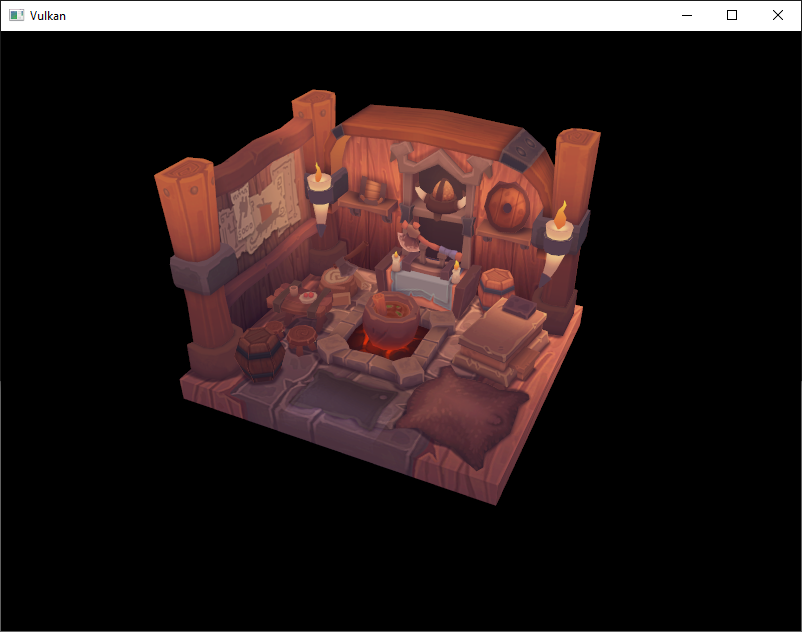
Just like with mipmapping, the difference may not be apparent straight away. On a closer look you'll notice that the edges are not as jagged anymore and the whole image seems a bit smoother compared to the original.
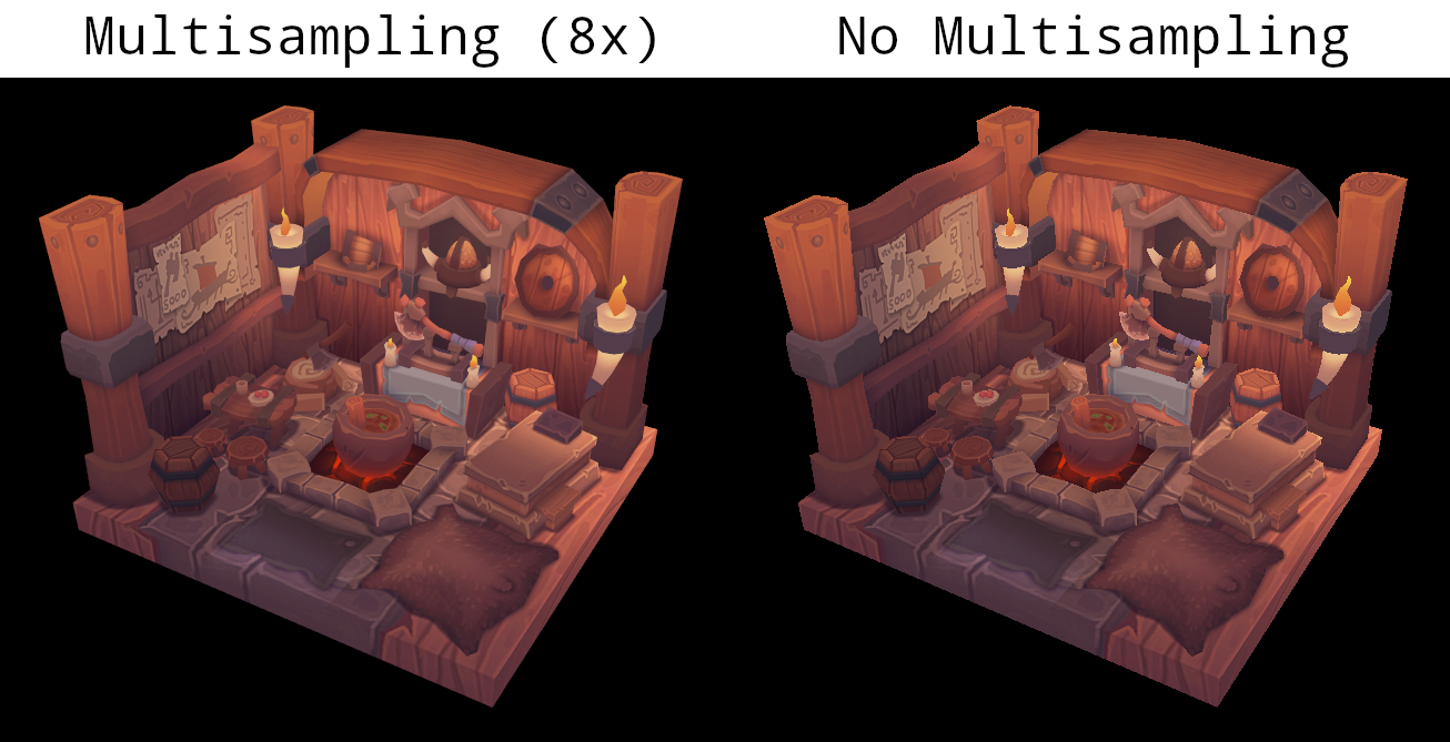
The difference is more noticeable when looking up close at one of the edges:
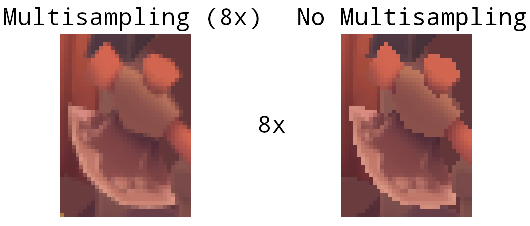
Quality improvements
There are certain limitations of our current MSAA implementation which may impact the quality of the output image in more detailed scenes. For example, we're currently not solving potential problems caused by shader aliasing, i.e. MSAA only smoothens out the edges of geometry but not the interior filling. This may lead to a situation when you get a smooth polygon rendered on screen but the applied texture will still look aliased if it contains high contrasting colors. One way to approach this problem is to enable Sample Shading which will improve the image quality even further, though at an additional performance cost:
private void createLogicalDevice() {
// ...
deviceFeatures.sampleRateShading(Constants.VK_TRUE);
// ...
}
private void createGraphicsPipeline() {
// ...
multisampling.sampleShadingEnable(Constants.VK_TRUE);
multisampling.minSampleShading(0.2f);
// ...
}
In certain scenarios the quality improvement may be noticeable:
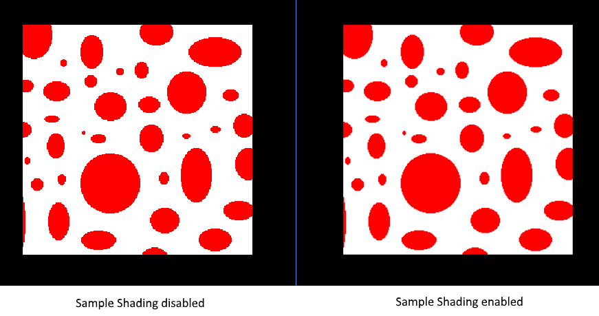
Conclusion
It has taken a lot of work to get to this point, but now you finally have a good base for a Vulkan program. The knowledge of the basic principles of Vulkan that you now possess should be sufficient to start exploring more of the features, like:
- Push constants
- Instanced rendering
- Dynamic uniforms
- Separate images and sampler descriptors
- Pipeline cache
- Multithreaded command buffer generation
- Multiple subpasses
- Compute shaders
The current program can be extended in many ways, like adding Blinn-Phong lighting, post-processing effects and shadow mapping. You should be able to learn how these effects work from tutorials for other APIs, because despite Vulkan's explicitness, many concepts still work the same.